
Production network
Production network
-
The production network involves the connections between the customer’s network and the two ToR ECS front-end, public data switches and the connections within the ECS rack. These connections act as the critical paths for in and out client requests and data (“north to south”), and internode traffic (“east to west”) for replication and processing requests as shown in the following figure for a single rack.

Figure 7. Network traffic flow in a single rack
For multirack, Gen1/2 and Gen3 EX300, EX500, EX3000 and EX5000 systems, internode traffic flows north to south and over to the customer network and to the other ECS racks as shown in the following figure.
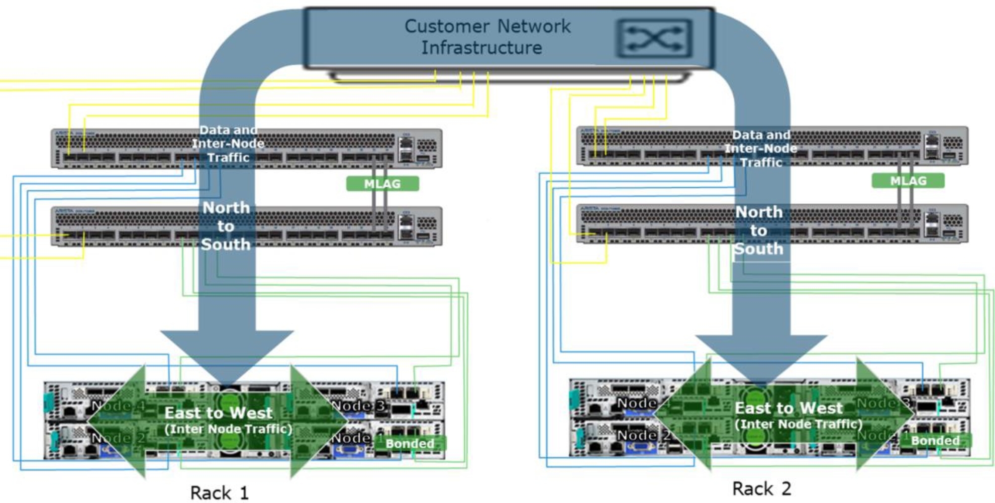
Figure 8. Network traffic flow in a multirack
Note: For Gen3 EXF900, it is designed with NVMe-oF architecture, the internode traffic will go through inside the private switch and dedicated aggregation switch to improve the performance.
Network connections in the production network as a best practice should be designed for high availability, resiliency, and optimal network performance.
ToR public switch configuration and node connectivity
The public ToR switches work in tandem using LACP/MLAG with the Arista switches in Gen1/2 appliances, and Virtual Link Trunking (VLT) with the Dell switches in Gen3 appliances. This configuration creates an HA network for the nodes in the rack. Similarly, if Cisco switches are used the vPC LAG protocol is used for HA. The aggregation of multiple ports results in higher bandwidth, resiliency, and redundancy in the data path.
Each node in the rack is connected to both switches through two NICs which are aggregated together using a Linux bonding driver. The node is configured to bond the two NICs into a single LACP bonding interface also known as a "mode 4" bond. This bonding interface connects one port to each switch as demonstrated in the following images.
The following two figures are examples of nodes bonded with a public switch pair.
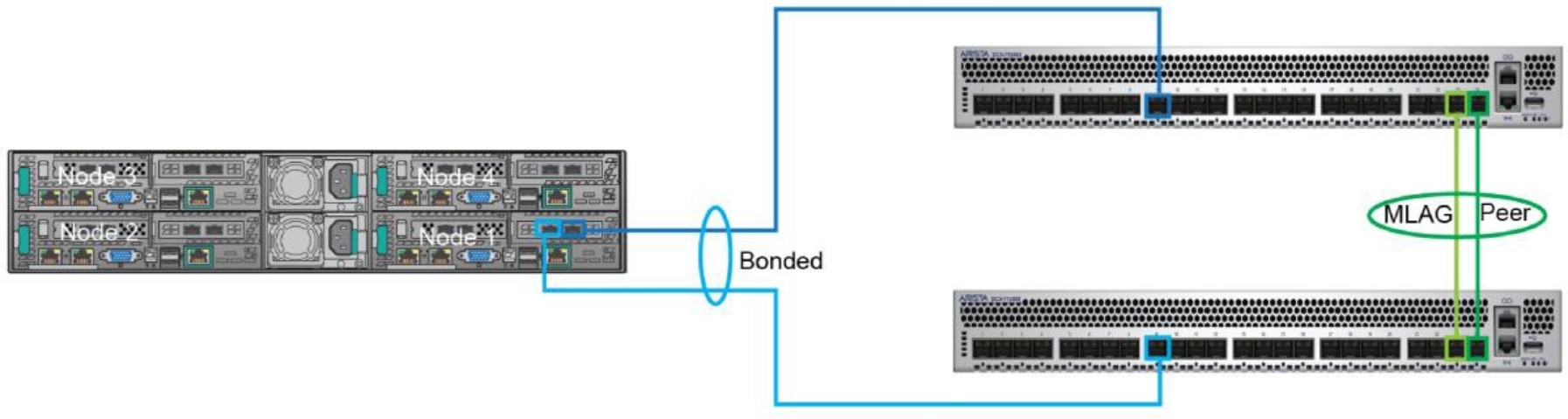
Figure 9. Gen1/2 node connectivity by MLAG
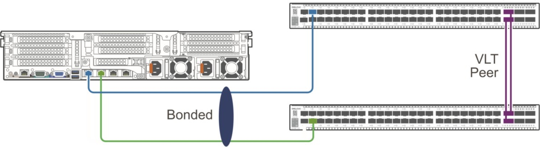
Figure 10. Gen3 node connectivity by VLT
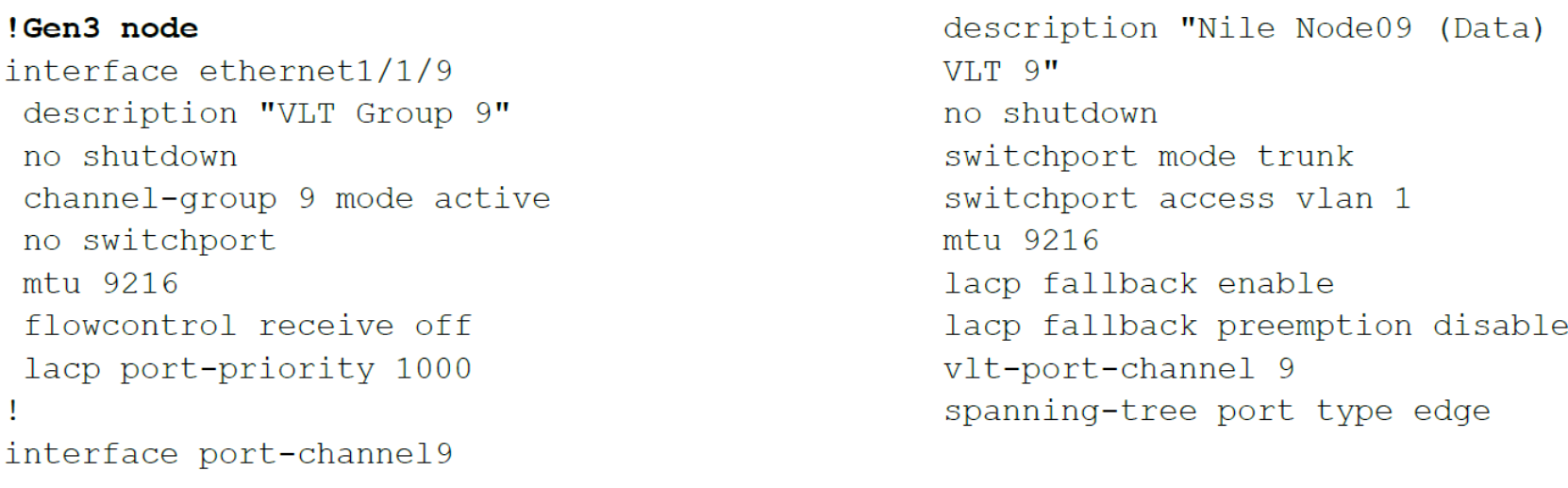
The terminal output on the next page displays snippets of the basic configuration files for the Gen1/2 and Gen3 node. LACP is a protocol that would build LAGs dynamically by exchanging information in Link Aggregation Control Protocol Data Units (LACDUs) relating to the link aggregation between the LAG. LACP sends messages across each network link in the group to check if the link is still active resulting in faster error and failure detection. The port channels on each switch are MLAG-ed together and can be visible from the nodes. They are configured to allow for fast connectivity using the spanning tree portfast command. This command places the ports in forwarding state immediately as opposed to the transition states of listening, learning and then forwarding which can cause 15 seconds of delay. Port channels are also set to lacp fallback to allow all ports within the port channel to fall back to individual switch ports. When the node’s ports are not yet configured as LAG, this setting allows for PXE booting from public switch ports of the nodes and forwarding of traffic.

The data switches are preconfigured on ECS supported switches. The configuration files for the data switches are on each node in directory. For example, Gen3 Dell switch configuration files are located inside /usr/share/emc-dell-firmware/config/ecs/.
Customer uplink configuration
Any networking device supporting Static Link Aggregation Group or IEEE 802.3ad Link Aggregation Control Protocol (LACP) can connect to the MLAG switch pair. With Static Link Aggregation, all settings are defined on all participating LAG components whereas LACP sends messages across each link in the group to check their state. An advantage of LACP over Static Link Aggregation is faster error or failure detection and handling.
Each Gen1/2 Arista public data switch has eight ports available to connect to the customer network, providing sixteen uplink ports per rack. Gen3 Dell switches each have eight 10/25 GbE and four 40/100 GbE ports, providing either sixteen or eight uplink ports per rack. See the appropriate (Gen1/2 or Gen3) Networks Guide for ECS Hardware for complete details including switch configuration examples.
For Gen1/2 appliances, similar to the ports used for the node, the eight uplink ports on each of the data switches are configured as a single LACP/MLAG interface. This configuration is shown below in the code output. The port channels are also configured to be in lacp fallback mode for customers who are unable to present LACP to the ECS rack. This mode will only be activated if no LACP is detected by the protocol. If there is no LACP discovered between the customer link and the ECS switches, the lowest active port will be activated and all other linked ports in the LAG will be disabled until a LAG is detected. At this point, there is no redundancy in the paths.
In addition, the data switches are not configured to participate in the customer’s spanning tree topology. They are presented as edge or host devices since a single LAG for the eight ports in each switch is created. It also simplifies the setup of the ECS switches in the customer network. Here is the output for public switches basic configuration file.
!Gen1/2 node
interface Ethernet1
description MLAG group 100
channel-group 100 mode active
lacp port-priority 1
!
interface Port-Channel100
description Customer Uplink (MLAG group 100)
port-channel lacp fallback
port-channel lacp fallback timeout 1
spanning-tree bpdufilter enable
mlag 100
!Gen3 node for 10G uplink
interface ethernet1/1/33:1
description "Customer Uplink 10G"
no shutdown
channel-group 80 mode active
no switchport
mtu 9216
flowcontrol receive off
!
interface port-channel80
description "Customer uplink 10G"
no shutdown
switchport mode trunk
switchport access vlan 1
mtu 9216
vlt-port-channel 80
spanning-tree bpdufilter enable
!
!Gen3 node for 25G uplink
interface ethernet1/1/41
description "Customer Uplink 25G"
no shutdown
channel-group 90 mode active
no switchport
mtu 9216
flowcontrol receive off
!
interface port-channel90
description "Customer Uplink 25G"
no shutdown
switchport mode trunk
switchport access vlan 1
mtu 9216
vlt-port-channel 90
spanning-tree bpdufilter enable
!
!Gen3 node for 100G uplink (40G uplink ports share with 100G uplink ports)
interface ethernet1/1/53
description "Customer Uplink 100G"
no shutdown
channel-group 100 mode active
no switchport
mtu 9216
flowcontrol receive off
!
interface port-channel100
description "Customer Uplink 100G"
no shutdown
switchport mode trunk
switchport access vlan 1
mtu 9216
vlt-port-channel 100
spanning-tree bpdufilter enable
!
!Gen3 node for 40G uplink (40G uplink ports share with 100G uplink ports)
interface ethernet1/1/53:1
description "Customer Uplink 40G"
no shutdown
channel-group 110 mode active
no switchport
mtu 9216
flowcontrol receive off
!
interface port-channel110
description "Customer Uplink 40G"
no shutdown
switchport mode trunk
switchport access vlan 1
mtu 9216
vlt-port-channel 110
spanning-tree bpdufilter enable
!
Note: In the Gen3 nodes, we use port channels 80, 90,100 and 110 to indicate different port speeds. See the ECS hardware guide for more information.
Connections from the customer network to the data switches can be linked in several different ways. For instance, they can be linked as a single link, as multi-link to a single switch using LACP, or as a multi-link to multiple switches using a multiple-switch LACP protocol like Arista MLAG, Dell VLT, or Cisco vPC. Customers are required to provide the necessary connection information to establish communication to the nodes in the rack.

Figure 11. Single customer switch with multiple links
The code below shows an example of a two port LAG for an ECS public switch and Cisco single switch with multiple links.
!Gen1/2 Arista configuration
interface Ethernet 1-2
channel-group 100 mode active
interface ethernet1/1/41-1/1/42
channel-group 100 mode active
no switchport
mtu 9216
!Customer Cisco configuration
interface Ethernet1/1
channel-group 100 mode active
interface Ethernet1/2
channel-group 100 mode active
Figure 12 exhibits a multiple port uplink to multiple switches with a LAG configuration. A better approach would be to configure more than two links per ECS switch as presented in Figure 13. The links should be spread in a bowtie fashion (links on each customer switch should be distributed evenly between the data switches) for redundancy and optimal performance during failures or scheduled downtime.
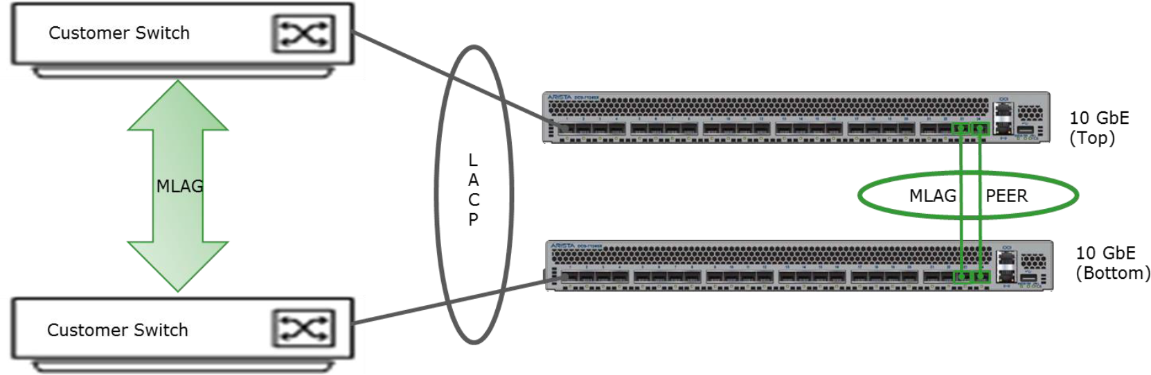
Figure 12. Multiple customer switches with single link per switch
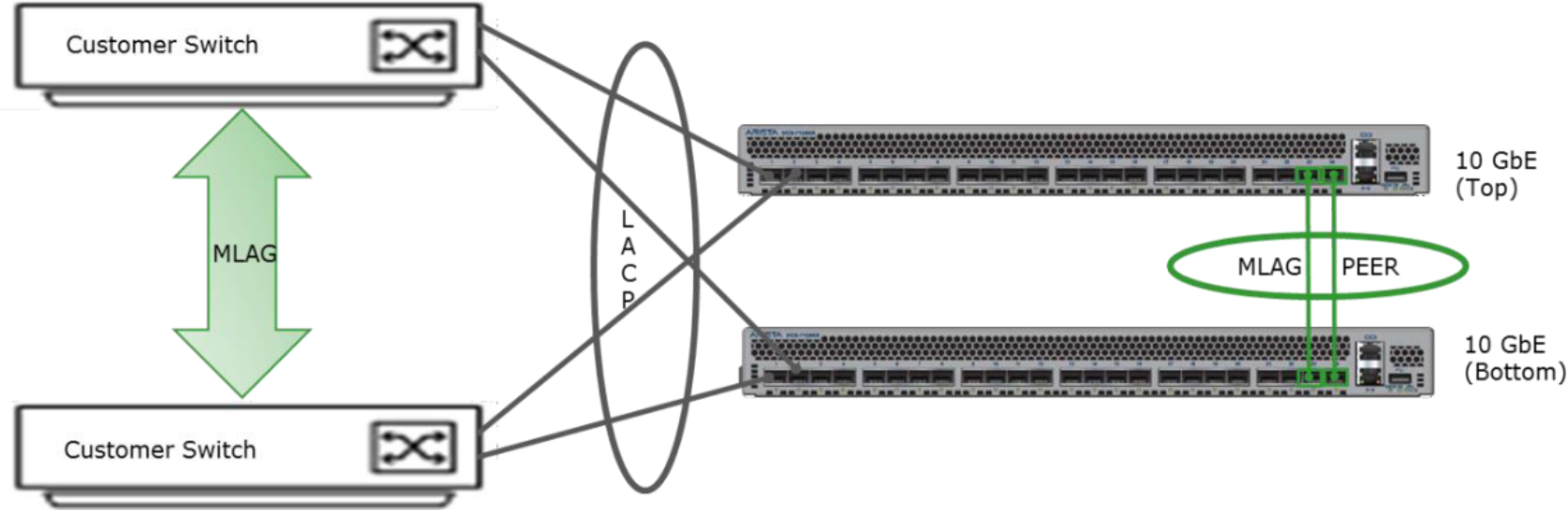
Figure 13. Multiple customer switches with multiple links per switch
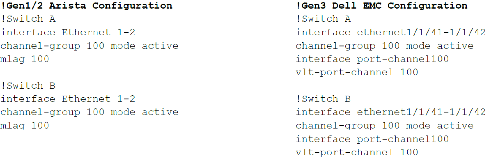
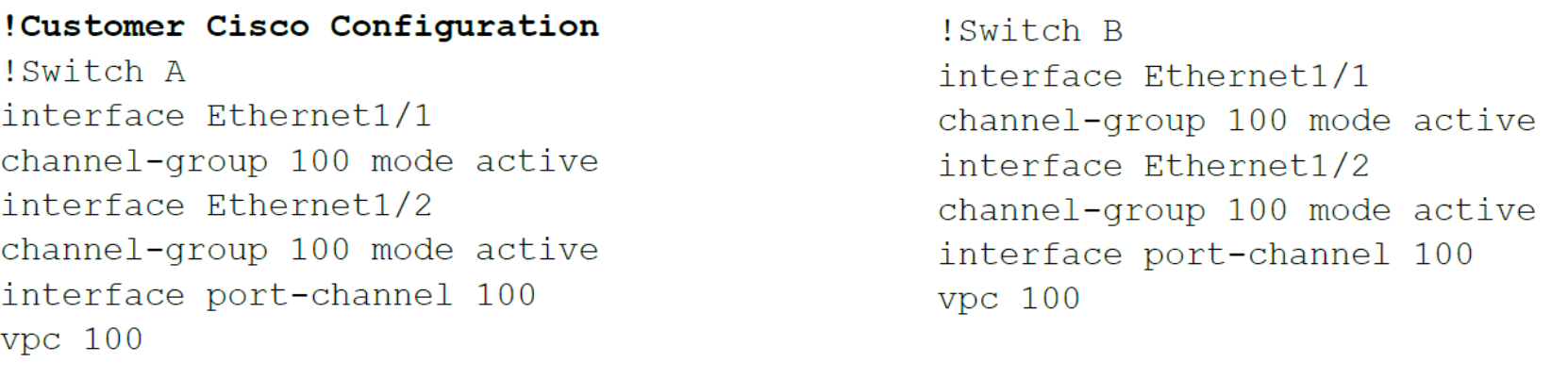
In either of these configurations, both port channels will need to be connected using a multiswitch LAG protocol like Arista MLAG or Cisco virtual Port Channel (vPC) to connect to the ECS MLAG switch pair port channel. Also, customers need to create port channels using LACP in active or passive mode on all switches participating in the multiswitch LAG. In the output below are sample configurations for Arista and Cisco with multiswitch LAG protocols definitions. Note the vPC or MLAG numbers on each switch would need to match to create a single port channel group.
Best practices:
- For multiple links, set up LACP on the customer switch. If LACP is not configured on customer switches to ECS switches, one of the data switches will have the active connection or connections. The port or ports connected to other data switch will be disabled until a LAG is configured. The connection or connections on the other switch will only become active if one switch goes down.
- Balance the number of uplinks from each switch for proper network load balancing to the ECS nodes.
- When using two customer switches, it is required to use multiswitch LAG protocols.
- For multirack environments of Gen1/2, Gen3 EX300, EX500, EX3000 and EX5000 systems, consider using an aggregation switch to keep internode traffic separated from customer core network.
Note: Gen1/2 switches are configured not to participate in the customer’s spanning tree topology. Gen3 switches are configured to participate in the customer’s spanning tree topology with Rapid Spanning Tree Protocol (rstp). For Gen3 switch configuration details see the ECS Networks Guide for EX300 and EX3000 (EX-Series) Hardware documentation.
Network configuration custom requests
Customers may have requirements needing modifications to ECS basic configuration files for the data switches. For instance, customers who require physical network isolation between traffic types for security purposes. As an example, the following figure is an example of multiple ports uplinked to multiple domains. In this setup, it would need changes in the data switches basic configuration files to support two LAGs on the uplinks and to change VLAN membership for the LAGs.
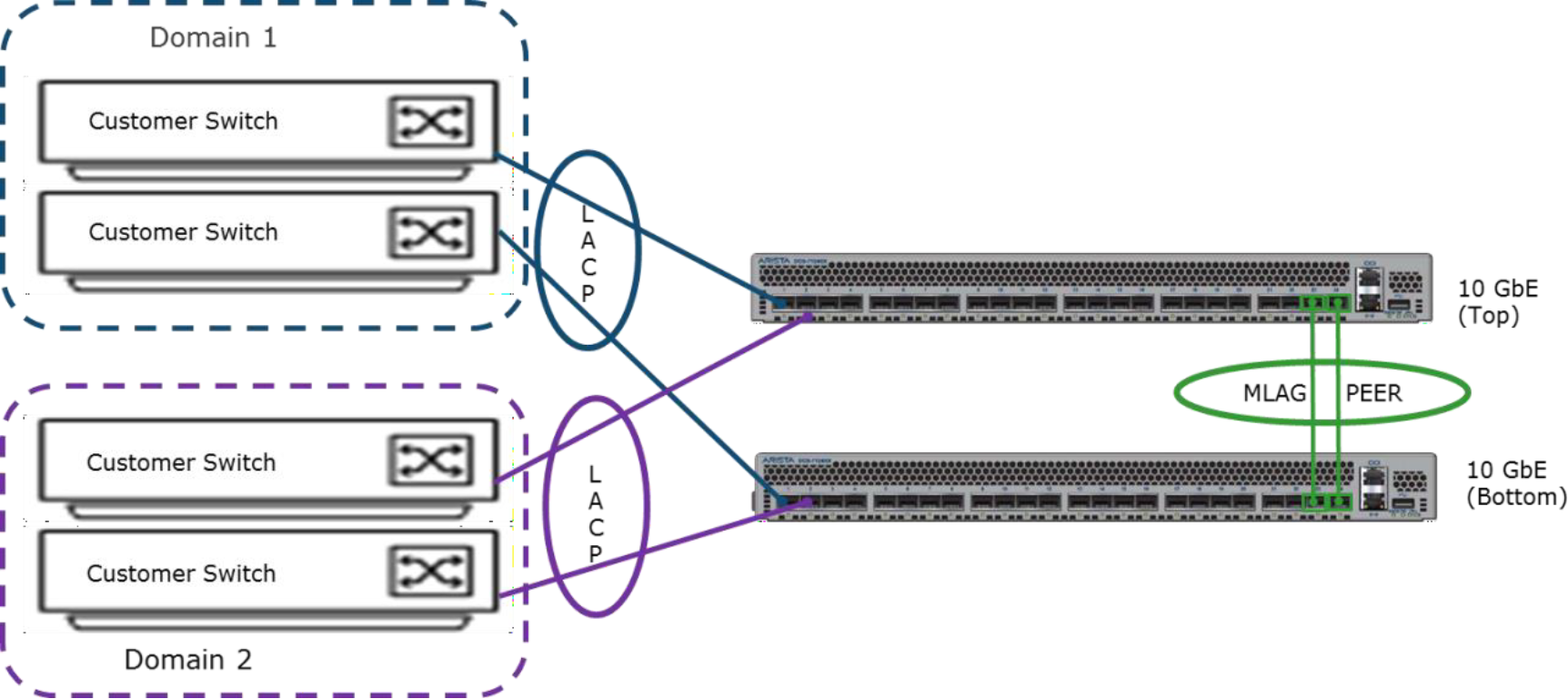
Figure 14. Multiple uplinked to multiple domains
Another example is if the customer needs to configure the uplinks for a specific VLAN. The VLAN membership should only be changed if the customer requirement is to set the uplink ports to VLAN trunk mode. Only the port channels for the uplink and nodes need to be changed to setup the VLAN. The output below shows a sample of how to change the VLAN membership. Both data switches would need to have the same VLAN configuration.
# Create new vlan
vlan 10
exit
# change to vlan trunk mode for uplink
interface port-channel100
switchport mode trunk
switchport trunk allowed vlan 10
# change vlan membership for access port to the nodes
interface port-channel1-12
switchport access vlan 10
copy running-config startup-config
Best practices:
- See the document ECS Appliance Features RPQ customer-provided switches configuration support for configuration changes.