
Internal private network
Internal private network
-
The internal private network, also known as the Nile Area Network (NAN), is mainly used for maintenance and management of the ECS nodes and switches within a rack and across racks. Ports on the management switch can be connected to another management switch on another rack, creating a NAN topology. From these connections, nodes from any rack or segment can communicate to any other node within the NAN. The management switch is split in different LANs to separate the traffic to specific ports on the switch for segment-only traffic, cluster traffic and customer traffic to RMM:
- Segment LAN: Includes nodes and switches within a rack
- Private.4 LAN: Includes all nodes across all racks
- RMM/iDRAC LAN: Includes uplink ports to customer LAN for RMM/iDRAC access from customer’s network
NAN topologies
The NAN is where all maintenance and management communications traverse within rack and across racks. A NAN database contains information such as IP addresses, MAC addresses, node name, and ID on all nodes within the cluster. This database is locally stored on every node and is synchronously updated by primary node using the setrackinfo command. Information on all nodes and racks within the cluster can be retrieved by querying the NAN database. One command that queries the NAN database is getrackinfo.
The racks are connected to the management switches on designated ports. These connections allow nodes within the segments to communicate with each other. There are different ways to connect the racks or rack segments together. Each rack segment is specified a unique color during installation and thus identifying the racks within the cluster. The figures below depict some of the topologies and give some advantages and disadvantages of each NAN topology.
The following figure shows a simple topology linearly connecting the segments through ports of the management switches in a daisy-chain fashion. The disadvantage of this topology is that when one of the physical links breaks, there is no way to communicate to the segment or segments that has been disconnected from the rest of the segments. This event causes a split-brain issue in NAN and forms a less reliable network.
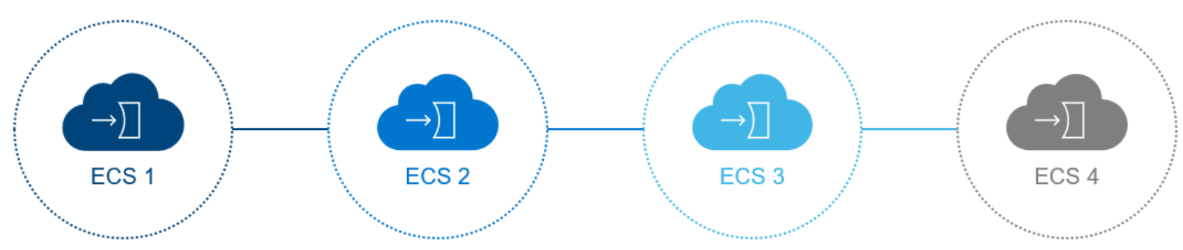
Figure 15. Linear or daisy chain topology
Another way to connect the segments is in a ring topology as illustrated in the following figure. The advantage of the ring topology over the linear is that two physical links would need to be broken to encounter the split-brain issue, proving to be more reliable.
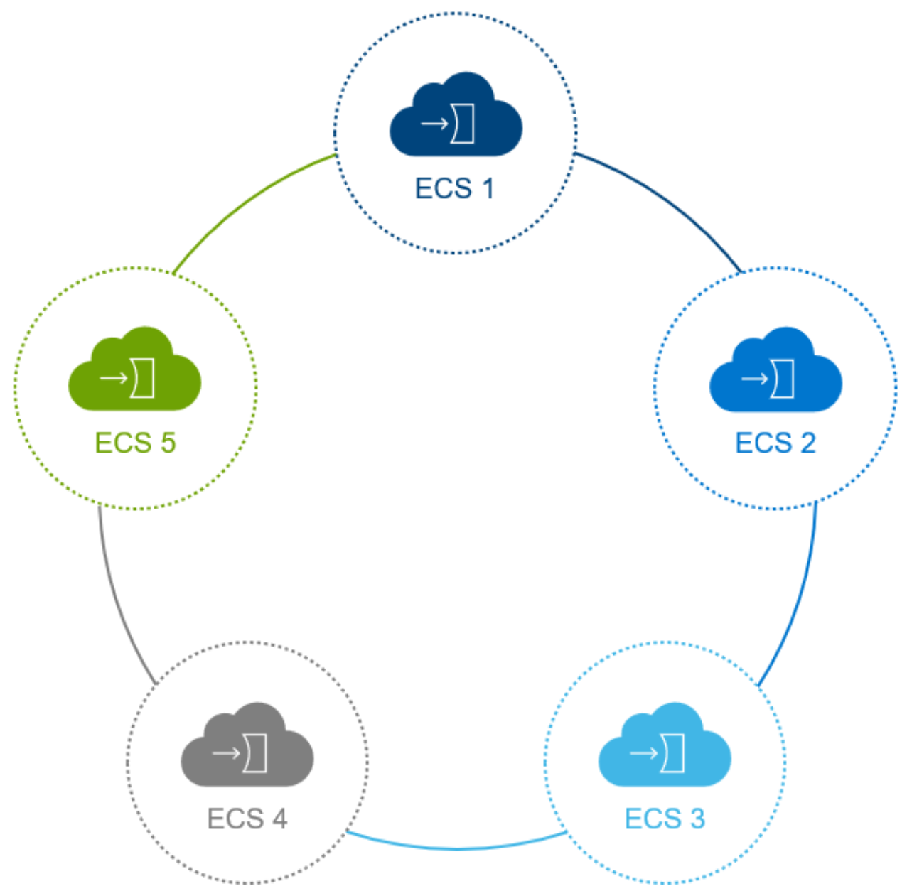
Figure 16. Ring topology
For large installations, the split-brain issue in the ring or linear topologies could be problematic for the overall management of the nodes. A star topology is recommended for an ECS cluster where there are ten or more racks or customers wanting to reduce the issues that ring or linear topologies pose. In the star topology, an aggregation switch, as shown in the following figure, would need to be added and would be an extra cost; however, it is the most reliable among the NAN topologies.
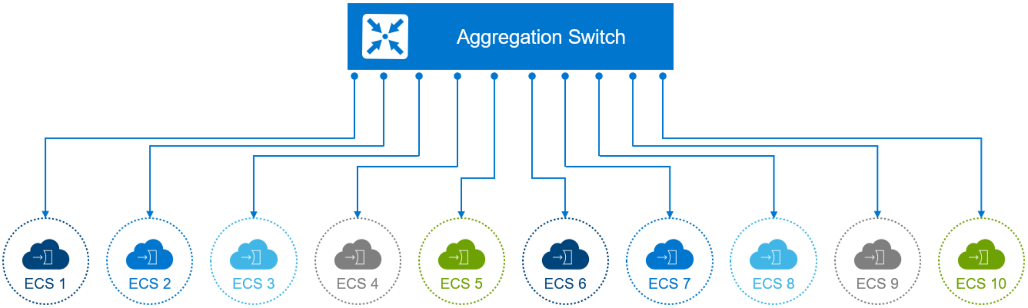
Figure 17. Star topology
Best practices:
- Do not use linear topology.
- For large installations of ten or more ECS racks, a star topology is recommended for better failover.
- EXF900 use dedicated aggregation switches for ECS racks, each node use port 53-56 for connecting.
Segment LAN
The Segment LAN logically connects nodes and switches within a rack to a LAN identified as VLAN 2. This LAN consists of designated ports on the management switch or switches and are referred to as the blue network. All traffic is limited to members of this segment for ease of management and isolation from the customer network and other segments within the cluster. The Ethernet ports on the nodes are configured with a private IP address derived from the segment subnet and node ID number. Thus, the IP address is of the form 192.168.219.{NodeID}. The IPs are not routable and packets are untagged. These addresses are reused by all segments in the cluster. To avoid confusion, it is not recommended to use these IP addresses in the topology file required when installing the ECS software on the nodes. There are several IP addresses that are reserved for specific uses:
- 192.168.219.254: Reserved for the primary node within the segment. Recall from the previous section that there is a primary node designated to synchronize the updates to the NAN database.
- 192.168.219.250: Reserved for the private switch (bottom)
- 192.168.219.251: Reserved for the private switch (top)
- 192.168.219.252: Reserved for the public switch (bottom)
- 192.168.219.253: Reserved for the public switch (top)
- 169.254.255.252: Reserved for the aggregation switch for EXF900 (bottom)
- 169.254.255.253: Reserved for the aggregation switch for EXF900 (top)
Note: Gen1/2 only have one private switch named turtle with 192.168.219.251.
Best practices:
- For troubleshooting a Gen1/2 node, administer the node through the segment LAN (connect a laptop to port 24) to not interfere configurations of other segments within the cluster.
- For troubleshooting a Gen3 node, the administrator can access the cluster by the tray which is connected with private switch named fox in port 34, or connect a laptop to port 36 in the fox switch.
Private.4 LAN
Multiple segment LANs are logically connected to create a single Cluster LAN for administration and access to the entire cluster. Designated interconnect ports on management switches provide interconnectivity between management switches. All members will tag their IP traffic with VLAN ID 4 and communicate through the IPv4 link local subnet. During software installation, all nodes in the rack are assigned a unique color number. The color number acts as the segment ID and is used together with the node ID to consist of the new cluster IP address for every node in the cluster. The IP addresses of the nodes in the cluster LAN will be in the form of 169.254.{SegmentID}.{NodeID}. This unique IP address would be the recommended IP address to specify in the topology file for the nodes within the cluster.
Best practices:
- ECS does not support IPv6, so do not enable IPv6 on these switches or send IPv6 packets.
- If troubleshooting a segment within the cluster, administer the segment through the Segment LAN to not affect the configuration of the entire cluster.
- Use the IP address in the topology file to provide a unique IP for all nodes within the cluster.
RMM/iDRAC access from customer network (optional)
RMM/iDRAC access from customer network is optional, and it is recommended to determine specific requirement from customer. A relevant use of the RMM/iDRAC connection would be for ECS software-only deployments where the hardware is managed and maintained by customers. Another use is when customers have a management station in which they would require RMM/iDRAC access to all hardware from a remote location for security reasons.
Note: For Gen1/2 ECS, RMM connect to the private switch named turtle; For Gen3 ECS, iDRAC connect to the private switch named fox.
For a Gen1/2 node, to allow for RMM connections from customer switch, Ports 51 and 52 on the management switch are configured in a hybrid mode. This configuration allows the ports to handle both tagged and untagged traffic. In this setup, the ports can be used for multiple purposes. The uplinks to the customer switch are on VLAN 6 and packets are untagged.
Best practices:
- Providing RMM to customer is optional and only available in Gen1/2 appliances.
- Determination should be made if customer access to RMM is absolutely required before configuration.
- Ensure that NAN traffic on VLAN 4 does not leak to customer network when adding RMM access to customer network.