
ECS switch configuration for network separation
ECS switch configuration for network separation
-
Depending on customer requirements, network separation may involve modification of the basic configuration files for the data switches. This section will explore examples of different network separation implementations in the switch level such as the default, single domain, single domain with public set as a VLAN, and physical separation.
Standard (default)
The default settings use configuration files that are bundled with ECS. In this scenario, there is no VLAN and there is only the public network. Also, there is no tagged traffic in the uplink connection. All ports are running in access mode. The following table and figure provide an example of a default ECS network setup with customer switches.
Table 2. Standard default switch configuration
Interface
VLAN ID
Tagged
Uplink connection
Public
None
No
MLAG:po100
No tagged traffic
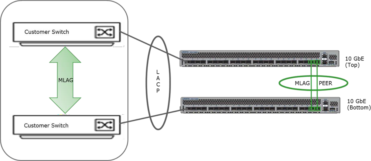
Figure 20. Standard default switch setup
Single domain
In a single domain, a LACP switch or an LACP/MLAG switch pair is configured on the customer side to connect to the ECS MLAG switch pair. Network separation is achieved by specifying VLANs for the supported traffic types. In the example in the following table and figure, data and replication traffic are separated into two VLANs and the management stays in the public network. The traffic on the VLANs will be tagged at the operating system level with their VLAN ID which in this case is 10 for data and 20 for replication traffic. The management traffic on the public network is not tagged.
Table 3. An example of single domain switch configuration
Interface
VLAN ID
Tagged
Uplink connection
Public
None
No
MLAG:po100
All named traffic tagged
Data
10
Yes
Repl
20
Yes
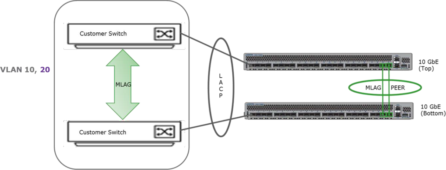
Figure 21. An example of a single domain switch with two VLANs
Both data switch configurations files would need to be modified to handle the VLANs in above example. The terminal output below shows how this can be specified for Arista switches. Things to note from the configuration file include:
- The switchports have been modified from access to trunk.
- VLANs 10 and 20 created to separate data and replication traffic are allowed. They also need to be created first.
- VLAN 1 corresponds to the public.
- If port channels are used, it will supersede and ignore Ethernet-level configurations.
This example shows a single domain’s switch settings with two VLANs for public switches.
vlan 10, 20
interface po1-12
switchport trunk native vlan 1
switchport mode trunk
switchport trunk allowed vlan 1,10,20
!For 7050S-52 and 7050SX-64, the last port channel is 24
interface po100
switchport mode trunk
switchport trunk allowed vlan 1, 10,20
Single domain and public VLAN
Customers may desire to have the public network in a VLAN and in this scenario, the traffic going through the public network will be tagged at the switch level and the other VLANs will be tagged at the operating system level. The following table and figure provide switch and configuration details for a single domain with public VLAN setup.
Table 4. An example of single domain switch configuration
Interface
VLAN ID
Tagged
Uplink connection
Public
100
Yes (switch)
MLAG:po100
All traffic tagged
Data
10
Yes (OS level)
Repl
20
Yes (OS level)
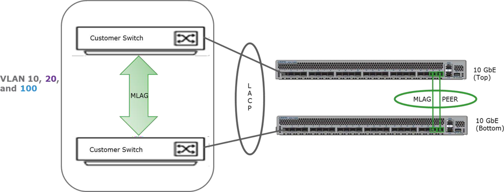
Figure 22. An example of single domain public VLAN switch setup
The settings within the configuration files of the data switches would need to be changed to include all the VLANs specified for network separation. As can be seen from the terminal output below, an update to the native VLAN is done to match the customer VLAN for public. In this example, the public VLAN is identified as VLAN 100.
Here is example code that shows a single domain with two VLANs and public VLAN settings for public switches.
vlan 10, 20, 100
interface po1-12
switchport trunk native vlan 100
switchport mode trunk
switchport trunk allowed vlan 10,20,100
interface po100
switchport mode trunk
switchport trunk allowed vlan 10,20,100
Physical separation
For physical separation, an example setup may include multiple domains on the customer network defined for each type of traffic. An example of the setup and details are shown in the following table and figure. As shown in the table, the public network is not tagged and will be on port channel 100, data traffic will be on VLAN 10, tagged and on port channel 101 and replication traffic will be on VLAN 20, tagged and on port channel 102. The three domains are not MLAG together.
Table 5. An example of physical separation configuration
Interface
VLAN ID
Tagged
Uplink connection
Public
None
No
MLAG:po100
Data
10
Yes
MLAG:po101
Repl
20
Yes
MLAG:po102
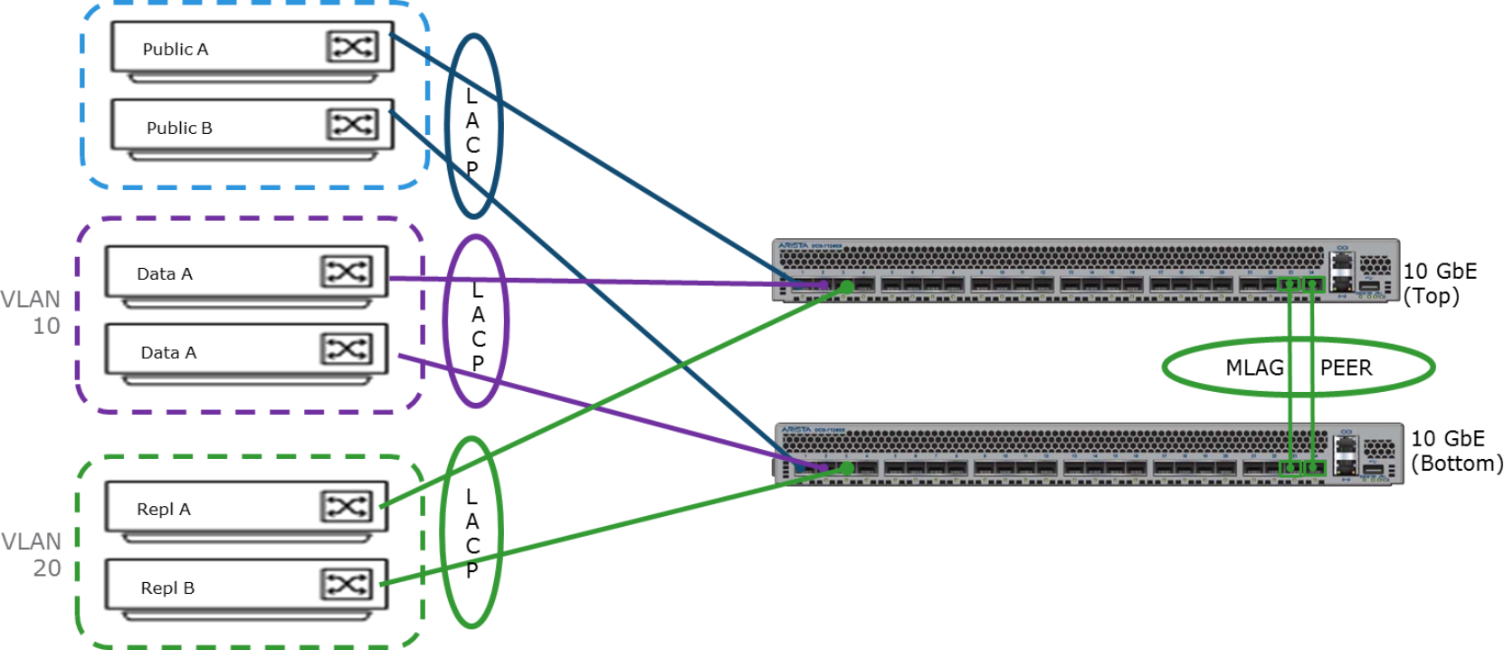
Figure 23. An example of physical separation setup
The terminal output below shows what the settings would be on the data switches for this configuration on Arista switches. Port-channel 100 is set up to remove uplink ports 2 through 8, leaving only the first uplink for the public network. Port-channel 101 defines the settings for the data traffic and port channel 102 is for the replication traffic where the corresponding VLANs are allowed and switchport is set to trunk. Connections to the data nodes are defined by interface po1-12.
For situations where customers would want the public network on a VLAN, the following table and the subsequent terminal output provide example details of the configuration. In this case, all traffic is tagged and public is tagged with ID 100, data traffic tagged with 10 and replication tagged with 20. Uplink connections and port channel 100 are set up as the trunk, and VLAN 10, 20, and 100 are allowed. The connections to the nodes defined in interface po1-12 are also set accordingly.
Table 6. Physical separation with public VLAN example
Interface
VLAN ID
Tagged
Uplink connection
Public
100
Yes (switch)
MLAG:po100
All traffic tagged
Data
10
Yes
Repl
20
Yes
Best practices:
- Network separation is optional. If used, it is important to determine fit and best configuration.
- Keep the management traffic within the public to reduce the number of static routes.
- Although it can have only default gateway in public, it is recommended to have at least one of the traffic types to be in the public network.