
None
None
-
The following diagram shows the network architecture of this solution:
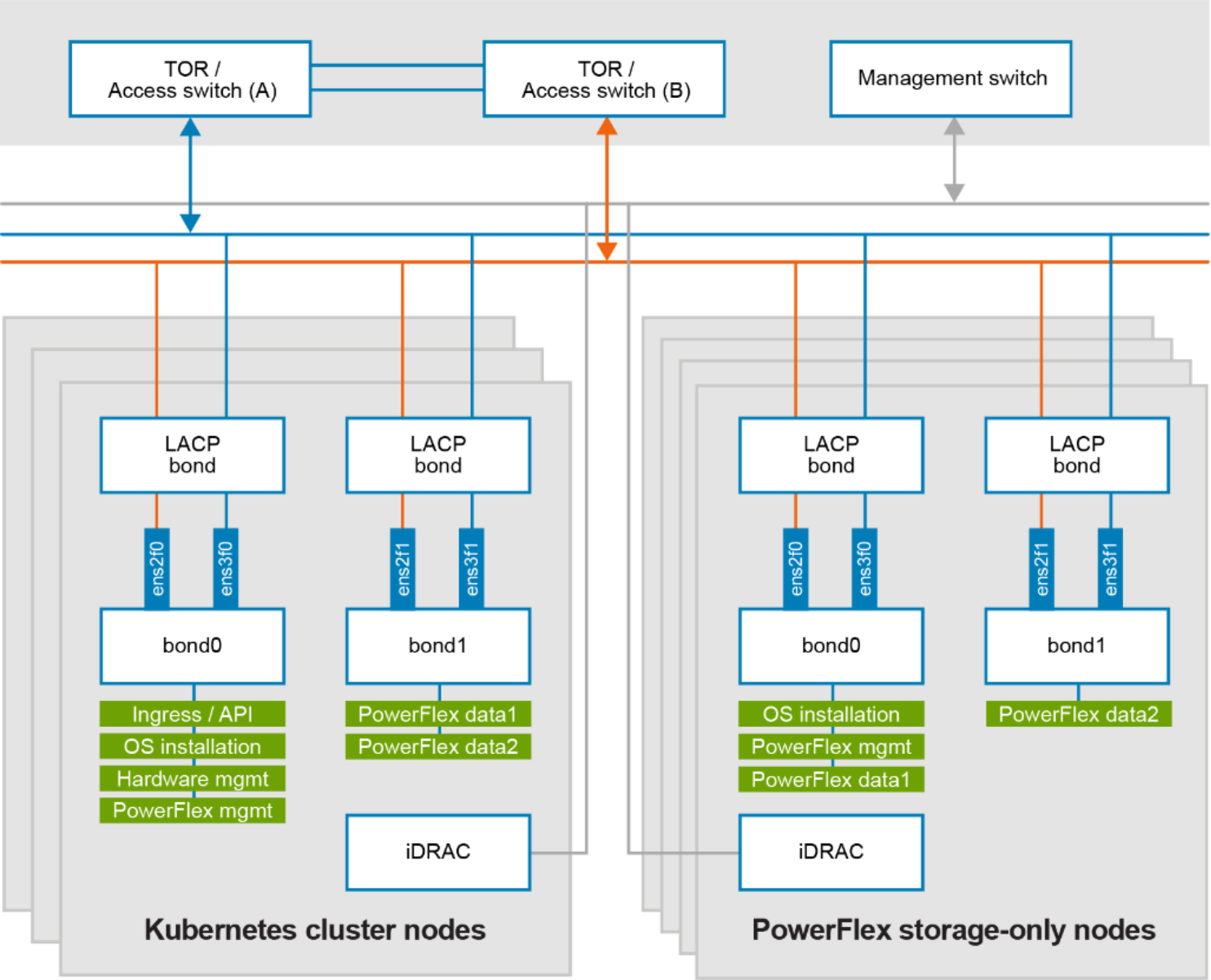
Figure 6. Network design of bare metal nodes and Powerflex SO nodes
At the physical layer, two supported Top of Rack (TOR) switches are used for redundancy and load-balancing purposes. A peer link is configured on both the TOR switches. VLANs are created to separate different traffic types on the network bonds.
The following table shows the different networks that are configured for this solution. See PowerFlex node VLAN setup for more information:
Table 2. Network details
Network type
VLAN ID
Ingress/API
105*
Operating System Installation
104
Hardware Management
101
PowerFlex Management
150
PowerFlex Data 1
152
PowerFlex Data 2
153
Note: 105*, is the network required for container Ingress/API traffic and need to Internet connectivity on this network.