
Container Storage Modules for Dell PowerFlex : Authorization Module
None
None
-
The following figure shows the logical architecture of this solution. The figure includes the PowerFlex compute layer with the Kubernetes environment, the PowerFlex storage layer, and the PowerFlex management components.
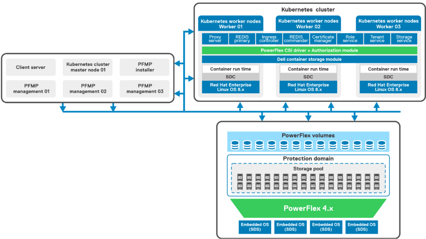
Figure 5. Logical design of Kubernetes Cluster with PowerFlex
The two-layer PowerFlex cluster consists of:
- PowerFlex compute-only node – Three PowerFlex R640 compute only nodes are installed with the Red Hat Enterprise Linux operating system. A Kubernetes cluster with a VM as control node and three bare metal worker nodes are deployed. The PowerFlex SDC component is installed on each worker node to host the workloads. The SDC enables PowerFlex storage to be used by applications running on the compute-only nodes.
- PowerFlex Storage node – Four PowerFlex R640 servers running the PowerFlex Embedded operating system. Each server is attached with SAS SSDs disks. The PowerFlex SDS component is installed on each server which contributes to the PowerFlex storage. The role of the SDS is to perform back-end I/O operations as requested by SDC.
- The PowerFlex storage cluster is deployed using the PowerFlex Manager, which automates the whole deployment process.
- PowerFlex management components – Three PowerFlex R640 servers running ESXi 7.x as the hypervisor hosts multiple PowerFlex management virtual machines (VMs), as follows:
- VMware vCenter Server Appliance (VCSA) deployed as a VM.
- Installer and PowerFlex management are deployed as VMs for deployment of PowerFlex 4.0.
- Network requirements such as Ethernet switching capable of L3 routing and supports trunking, L2 VLAN ID and tagging, VLAN names and numbers, and Port-channel with link aggregation control protocol (LACP) are met.
- NTP is configured for correct time synchronization for ESXi hosts, VMs, and all the bare metal servers.
- DNS and PTR records are set up and properly configured.
For more information about the hardware and operating system that is used in this solution, see Configuration details.