
In this set of tests, the Dell EMC switches and Cisco switches have been configured with their respective device redundancy technologies.
Rapid PVST+ is configured on the Cisco switches and RSTP on the Dell EMC switches. Both rapid spanning tree protocol (RSTP) and rapid per-VLAN spanning tree (RPVST+) modes of spanning tree protocol is supported in VLT mode. Two sets of tests were performed using the following configuration:
- In the first test, Cisco switches act as the root bridge for the respective VLANs
- Dell EMC switch as the root bridge

Cisco Nexus as root
The information that is provided in this section allows you to test the Cisco Nexus as the root bridge for the VLANs.
Test steps
The following test steps were conducted with Ixia IxExplorer to simulate a fail-over scenario:
- Create two tagged streams, where VLAN ID 10 is sourced from port 1 with MAC address 1, to destination port 3, and port 4.Note: For destination port 3 and port 4, use MAC destination addresses 3 and 4.
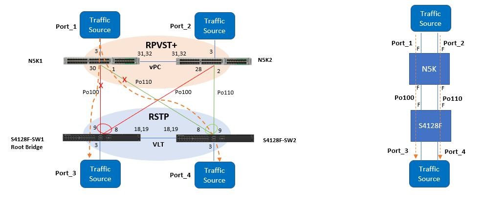
- Using the diagram as a reference, verify that tagged VLAN 20 traffic from the Port 1 traffic source is going through the N5K1 Cisco switch.
- Shut down port-channel 100 and port-channel 110 on N5K1 to simulate a fail-over scenario and check for any traffic disruptions.
- Verify that the data flow from Port 1 to Port 3 and Port 4 flows through the vPC port-channel to N5K2, and down through each respective link.
- Recover both ports, check for traffic disruption, and ensure that N5K1 becomes the root bridge.
- Shut down port 30 and port 1 on N5K1 and measure for traffic loss.
Results
To understand the results achieved, we must look at the interconnections between switches. When vPC and VLT are configured on the Cisco and Dell EMC switches respectively, a 4-member port-channel link is created between the switches. On the Dell EMC switch, once the discovery interfaces are configured on both the nodes, port-channel 1000 is automatically configured. The ports should be configured as no switchport from the default Layer-2 mode while configuring the discovery interfaces. From the S4128F perspective, 1/1/18 and 1/1/19 interfaces form the discovery interfaces/VLTi (Po-1000) on the VLT Peer1(S4128-SW1). Similarly, 1/1/18 and 1/1/19 interfaces form the discovery interface on VLT Peer2 (S4128-SW2).
Port-channel 100 is configured on S4128-SW1 and port-channel 110 on S4128-SW2. VLANs 10 and 20 are mapped to both the port channels. The VLAN membership is shown in the following figure:
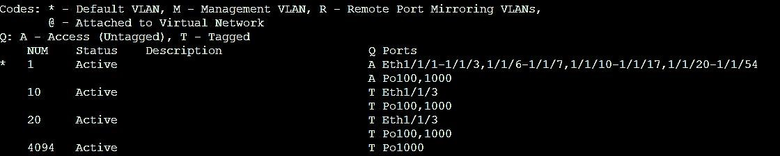
From the Cisco N5K perspective, by shutting down Po100 locally, Po110 continues to forward the traffic since both port channels are continuously forwarding. VLT ports, similar to vPC ports, are always in the forwarding state by default as per the feature implementation. Shutting down the individual links on the Dell EMC switch made no difference on the results because there are three available links forwarding.
The following code examples show the spanning tree link status for all four switches.
S4128-SW1# show spanning-tree active
Spanning tree enabled protocol rstp with force-version rstp
Executing IEEE compatible Spanning Tree Protocol
Root ID	Priority 24577, Address 547f.eeac.13c
Bridge ID	Priority 32768, Address f48e.385f.3dca

Interface       Designated
Name            PortID   Prio Cost Sts Cost BridgeID PortID
ethernet1/1/3   128.524  128  2000 FWD 501  32768    f48e.385f.3dca 128.524
port-channel100 128.2517 128  500  FWD 1    32769    0023.04ee.be01 144.99

Interface
Name            Role PortID   Prio Cost Sts Cost Link-type Edge
ethernet1/1/3   Desg 128.524  128  2000 FWD 501  AUTO      No
port-channel100 Root 128.2517 128  500  FWD 1    AUTO      No
S4128-SW2# show spanning-tree active
Spanning tree enabled protocol rstp with force-version rstp
Executing IEEE compatible Spanning Tree Protocol
Root ID Priority 24577, Address 547f.eeac.13c1
Bridge ID Priority 32768, Address 6400.6af6.faf4
Interface Designated
Name PortID Prio Cost Sts Cost BridgeID PortID
ethernet1/1/3 128.524 128 2000 FWD 502 32768 6400.6af6.faf4 128.524
port-channel110 128.2517 128 500 FWD 502 32768 6400.6af6.faf4 128.2517
Interface
Name Role PortID Prio Cost Sts Cost Link-type Edge
ethernet1/1/3 Desg 128.524 128 2000 FWD 502 AUTO No
port-channel110 Root 128.2517 128 500 FWD 502 AUTO No | |
Dell EMC as the root
The S4128-SW1 switch is configured as the root bridge in this test case. The figure below shows how the traffic flow is sent from port 1, to port 3 and to port 4.
Test steps
- Create two tagged streams, where VLAN ID 10 and VLAN ID 20 are sourced from port 1 with MAC address 1, to destination port 3, and port 4.
- Using the diagram as a reference, verify that tagged VLAN 20 traffic from the Port 1 traffic source is going through the N5K1 Cisco switch.
- Shut down port-channel 100 and 110 on N5K1 to simulate a fail-over scenario and to check for traffic disruption.
- To check for traffic disruptions, shut down port 30 and port 1.
- Recover port 30 and port 1 to check for any measurable traffic disruption.
- Repeat steps 4 and 5 and source traffic from port 3 to port 1 and port 2.
Results
The results for both tests were identical.