
Configure a jump host port
Configure a jump host port
-
VxRail Manager is used for VxRail deployments. The VxRail Manager VM automatically runs on the master VxRail node, which is the node with the lowest VxRail serial number.
Note: Before VxRail deployment, the VxRail Manager is accessible on an untagged port on the SFS Client Management VLAN (VLAN 4091 by default). The default IP address is 192.168.10.200.
VxRail Manager is accessed by connecting a laptop computer or a jump host directly to any available leaf switch port, as shown in Figure 41.
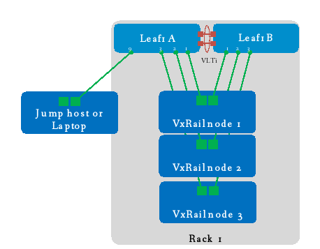
Figure 41. Jump host connected leaf switch for VxRail deployment
This section covers the configuration of a leaf switch port for connection to a jump host or laptop computer (referred to only as a jump host for the remainder of this guide).
Change native port speed on S5200 series switches
If the jump host has a 1 GbE or 10 GbE NIC, and it is connected to a 25 GbE port on an S5200 series switch, the switch port used must be changed from its native 25 GbE speed to 10 GbE for the port to come up.
If the jump host has a 1 GbE or 10 GbE NIC, and is connected to a 10 GbE port on an S4100 series leaf switch, or has a 25 GbE NIC and connects to an S5200 series leaf switch, leave the port at its native speed, skip this section, and go to Configure the jump host interface.
Note: When in 10 GbE mode, an S5200 series switch port will autonegotiate to 1 GbE when connected to a 1 GbE NIC. To connect a jump host with a 1 GbE BASE-T or 10 GbE BASE-T port to an SFP port on the leaf switch, use a Dell EMC supported SFP-1G-T or SFP-10G-T adapter.
Determine the port group
Determine the port group containing the port that the jump host will use. This is done by referencing the table below for S5200 series switches, or by running the show port-group command from the leaf switch CLI. For example, if the jump host is connected to port 1/1/9, it is in port group 1/1/3.
Table 9. S5200 series port-group numbers and speeds
Native physical interface name
Port group number
Native speed
Non-native speed
Non-native logical interface name
Applicable switches
Eth 1/1/1-1/1/4
Eth 1/1/5-1/1/8
Eth 1/1/9-1/1/12
Eth 1/1/13-1/1/16
Eth 1/1/17-1/1/20
Eth 1/1/21-1/1/24
Eth 1/1/25-1/1/28
Eth 1/1/29-1/1/32
Eth 1/1/33-1/1/36
Eth 1/1/37-1/1/40
Eth 1/1/41-1/1/44
Eth 1/1/45-1/1/48
Eth 1/1/49-1/1/52
Eth 1/1/53-1/1/56
Eth 1/1/57-1/1/60
Eth 1/1/61-1/1/64
Eth 1/1/65-1/1/68
Eth 1/1/69-1/1/72
Eth 1/1/73-1/1/76
Eth 1/1/77-1/1/80
Eth 1/1/81-1/1/84
Eth 1/1/85-1/1/88
Eth 1/1/89-1/1/92
Eth 1/1/93-1/1/96
1/1/1
1/1/2
1/1/3
1/1/4
1/1/5
1/1/6
1/1/7
1/1/8
1/1/9
1/1/10
1/1/11
1/1/12
1/1/13
1/1/14
1/1/15
1/1/16
1/1/17
1/1/18
1/1/19
1/1/20
1/1/21
1/1/22
1/1/23
1/1/24
25g-4x
25g-4x
25g-4x
25g-4x
25g-4x
25g-4x
25g-4x
25g-4x
25g-4x
25g-4x
25g-4x
25g-4x
25g-4x
25g-4x
25g-4x
25g-4x
25g-4x
25g-4x
25g-4x
25g-4x
25g-4x
25g-4x
25g-4x
25g-4x
10g-4x
10g-4x
10g-4x
10g-4x
10g-4x
10g-4x
10g-4x
10g-4x
10g-4x
10g-4x
10g-4x
10g-4x
10g-4x
10g-4x
10g-4x
10g-4x
10g-4x
10g-4x
10g-4x
10g-4x
10g-4x
10g-4x
10g-4x
10g-4x
Eth 1/1/x:1
Eth 1/1/x:1
Eth 1/1/x:1
Eth 1/1/x:1
Eth 1/1/x:1
Eth 1/1/x:1
Eth 1/1/x:1
Eth 1/1/x:1
Eth 1/1/x:1
Eth 1/1/x:1
Eth 1/1/x:1
Eth 1/1/x:1
Eth 1/1/x:1
Eth 1/1/x:1
Eth 1/1/x:1
Eth 1/1/x:1
Eth 1/1/x:1
Eth 1/1/x:1
Eth 1/1/x:1
Eth 1/1/x:1
Eth 1/1/x:1
Eth 1/1/x:1
Eth 1/1/x:1
Eth 1/1/x:1
S5212/S5224/S5248/S5296
S5212/S5224/S5248/S5296
S5212/S5224/S5248/S5296
S5224/S5248/S5296
S5224/S5248/S5296
S5224/S5248/S5296
S5248/S5296
S5248/S5296
S5248/S5296
S5248/S5296
S5248/S5296
S5248/S5296
S5296
S5296
S5296
S5296
S5296
S5296
S5296
S5296
S5296
S5296
S5296
S5296
Note: Changing the speed is done for all ports in the port group. In this example, setting port group 1/1/3 to 10g-4x changes ports 1/1/9-1/1/12 to 10 GbE, and the ports are renamed 1/1/9:1-1/1/12:1.
Change the port-group speed in the SFS GUI
In this section, port group 1/1/3 is changed from its 4x25 G native speed to 4x10 G to accommodate a jump host connected to port 1/1/9 on S5248F-Leaf1A.
- Select the Rack, Switch, and Port group. Set Breakout Capabilities to 4X10GEFixedFormFactor, as shown in Figure 42.
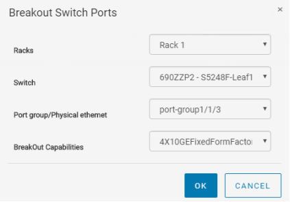
Figure 42. Configure switch ports
- Click OK to apply the setting.
Configure the jump host interface
The jump host interface is configured as follows:
- On the SFS GUI Home page, click 2. Configure Jump Host.
- In the Configure Jump Host window:
- Enter a Name, such as Jump Host 1.
- (Optional) Enter a Description
- Select the Rack, for example, Rack 1.
- Select the Switch, for example, Leaf1A.
- Select the Configured Interface that the jump host uses. In this example, it is 1/1/9:1.
Note: Port 1/1/9 was automatically renamed to 1/1/9:1 when its port group was changed from its native setting of 4x 25 GbE to 4x 10 GbE.
- Next to Untagged Network, leave the network set to Client_Management_Network, as shown in Figure 43.
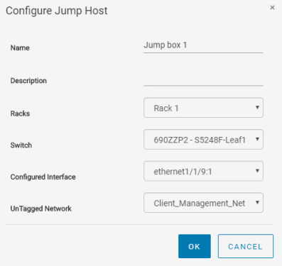
Figure 43. Configure jump host
- Click OK to apply the settings.
The jump host interface is added as an untagged member of the Client_Management_Network (VLAN 4091 by default).
To validate, run the show virtual-network command at the Leaf1A switch CLI.
Note: The output below is with an L3 uplink. If an L2 uplink to the external network is configured, the External Management Network, VLAN 1811 in this guide, also appears in the command output along with the L2 uplink port channel as a member. An output is shown in the Show command output on Leaf1A section of the L2 uplink configuration chapter.
VLAN 3939 contains port channel 1000 (the VLTi) and the three interfaces connected to the VxRail nodes, 1/1/1-1/1/3. VLAN 4091 contains port channel 1000, the three interfaces connected to the VxRail nodes, and the jump host port, ethernet 1/1/9:1.
Note: The jump host port is only configured on one of the leaf switches.
S5248F-Leaf1A# show virtual-network
Codes: DP - MAC-learn Dataplane, CP - MAC-learn Controlplane, UUD - Unknown-Unicast-Drop
Un-tagged VLAN: 4080
Virtual Network: 3939
Description: In-band SmartFabric Services discovery network
VLTi-VLAN: 3939
Members:
VLAN 3939: port-channel1000, ethernet1/1/1, ethernet1/1/2, ethernet1/1/3
VxLAN Virtual Network Identifier: 3939
Source Interface: loopback2(172.30.0.0)
Remote-VTEPs (flood-list):
Virtual Network: 4091
Description: Default untagged network for client onboarding
VLTi-VLAN: 4091
Members:
Untagged: ethernet1/1/1, ethernet1/1/2, ethernet1/1/3, ethernet1/1/9:1
VLAN 4091: port-channel1000
VxLAN Virtual Network Identifier: 4091
Source Interface: loopback2(172.30.0.0)
Remote-VTEPs (flood-list):
Configure the jump host IP addresses
By default, the initial VxRail Manager IP address is 192.168.10.200/24, and it is in VLAN 4091. After the initial configuration, the VxRail Manager address changes to its new address on the External Management VLAN (VLAN 1811 in this example). The new VxRail Manager address used in this guide is 172.18.11.72/24 per the planning data in Table 4.
During installation, the jump host must be able to reach both the initial and new VxRail Manager addresses, so two addresses are configured on its network adapter, one for each network.
The IP addresses are configured on the jump host NIC in this example as follows:
- 192.168.10.201/24, to communicate with the initial VxRail Manager address, 192.168.10.200/24
- 172.18.11.201/24, to communicate with the new VxRail Manager address, 172.18.11.72/24
Note: Both addresses may be configured simultaneously if the network adapter supports it, or in sequence if required. During VxRail deployment, the jump host port on the switch is automatically moved from VLAN 4091 to the External Management VLAN, along with VxRail Manager. Since the jump host port on the switch is untagged in VLAN 4091, and will also be untagged in the External Management VLAN, no VLAN information is configured on the jump host NIC.
Once the jump host has been configured with an IP address on the 192.168.10.0/24 network, verify the jump host can communicate with VxRail Manager by pinging 192.168.10.200 from the jump host.
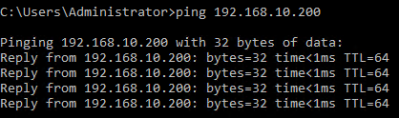
Figure 44. Jump host successfully pings VxRail manager