
As shown in Figure 11, the Scale Out Fabric interconnects the NICs coupled with the GPUs in an XE9680 to build a GPU cluster including more than a single node. The Scale Out Fabric is used by the set of GPUs composing a GPU cluster to exchange AI workload parameters.
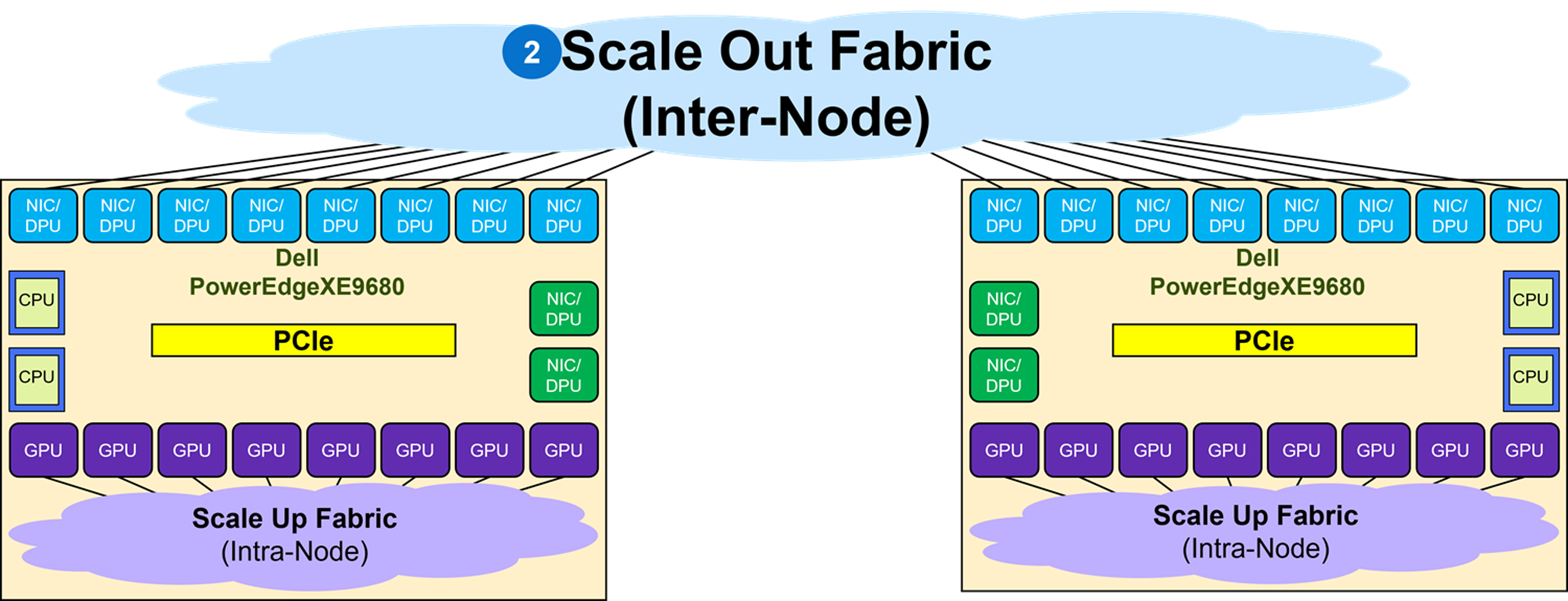
When deploying a Scale Out fabric, keep the following in mind:
- No EVPN VXLAN BGP is deployed as the networking protocol since multi-tenancy GPU service is not a requirement. It is best to deploy plain BGP as the network protocol in the fabric.
- Switch redundancy, such as MC-LAG is not needed. Link redundancy is achieved by multiple active links between leaf and spine, as well as GPU connections to multiple leaf switches.
These are guidelines to keep in mind and it is certainly not an exhaustive networking design checklist. Fabric configuration requires detailed planning and design throughout the entire deployment cycle.
Multiple topologies can be used to build a Scale Out Fabric:
- Single Switch topology
- TOR-Wired Clos topology
- Pure Rail topology
- Rail Optimized topology
Single switch topology
The first and simplest Scale Out Fabric topology is the single switch topology, which is the simplest instance of a TOR-Wired Clos topology. Figure 12 shows the connectivity properties of the TOR-Wired Clos topology.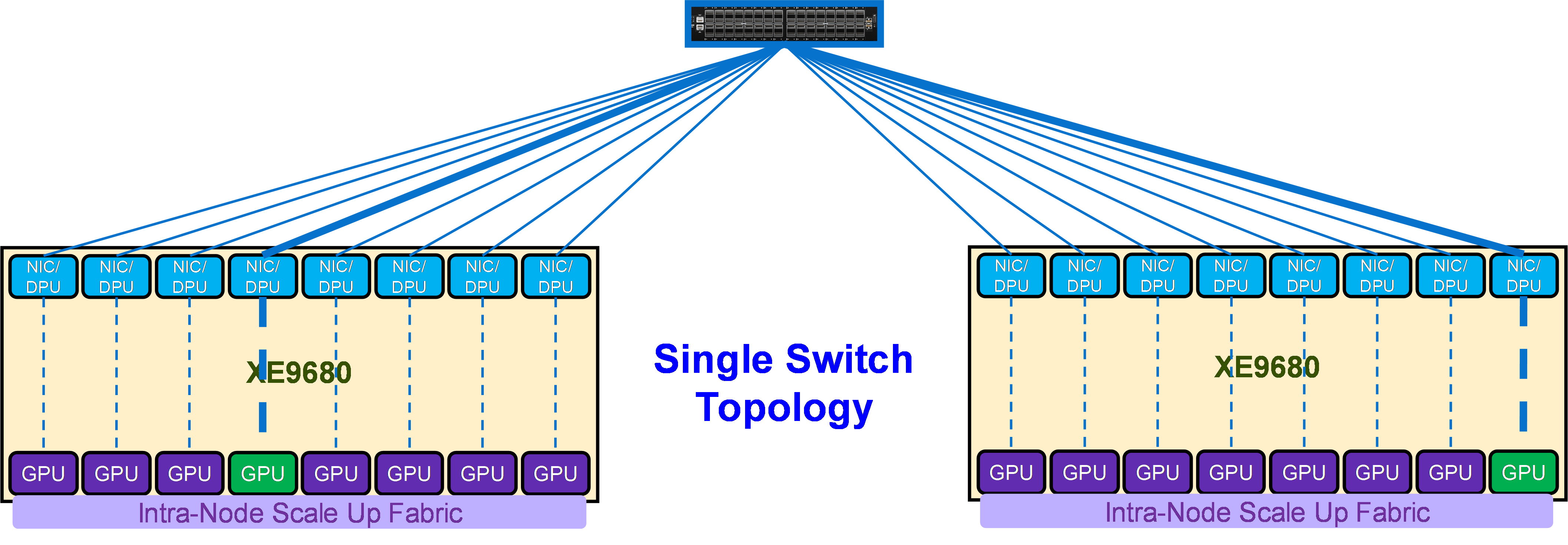
As shown in Figure 12, this topology enables direct Scale Out Fabric communication between any GPU pairs without involving the Scale Up Fabric. For example, GPU 4 on Server 1 can directly communicate through NIC 4 on Server 1 with GPU 8 on Server 2, because the single switch topology (or TOR-Wired Clos topology) enables NIC 4 on Server 1 to communicate with NIC 8 on Server 2, and NIC 8 on Server 2 is coupled with GPU 8 on Server 2.
The following items characterize a single switch topology:
- Single Dell PowerSwitch Z9864 (or Z9664F-ON) switch
- 1 to 16 (or 1 to 8) Dell PowerEdge XE9680s
- 8 to 128 (or 8 to 64) GPU cluster
- Layer 2 or Layer 3 with RoCEv2
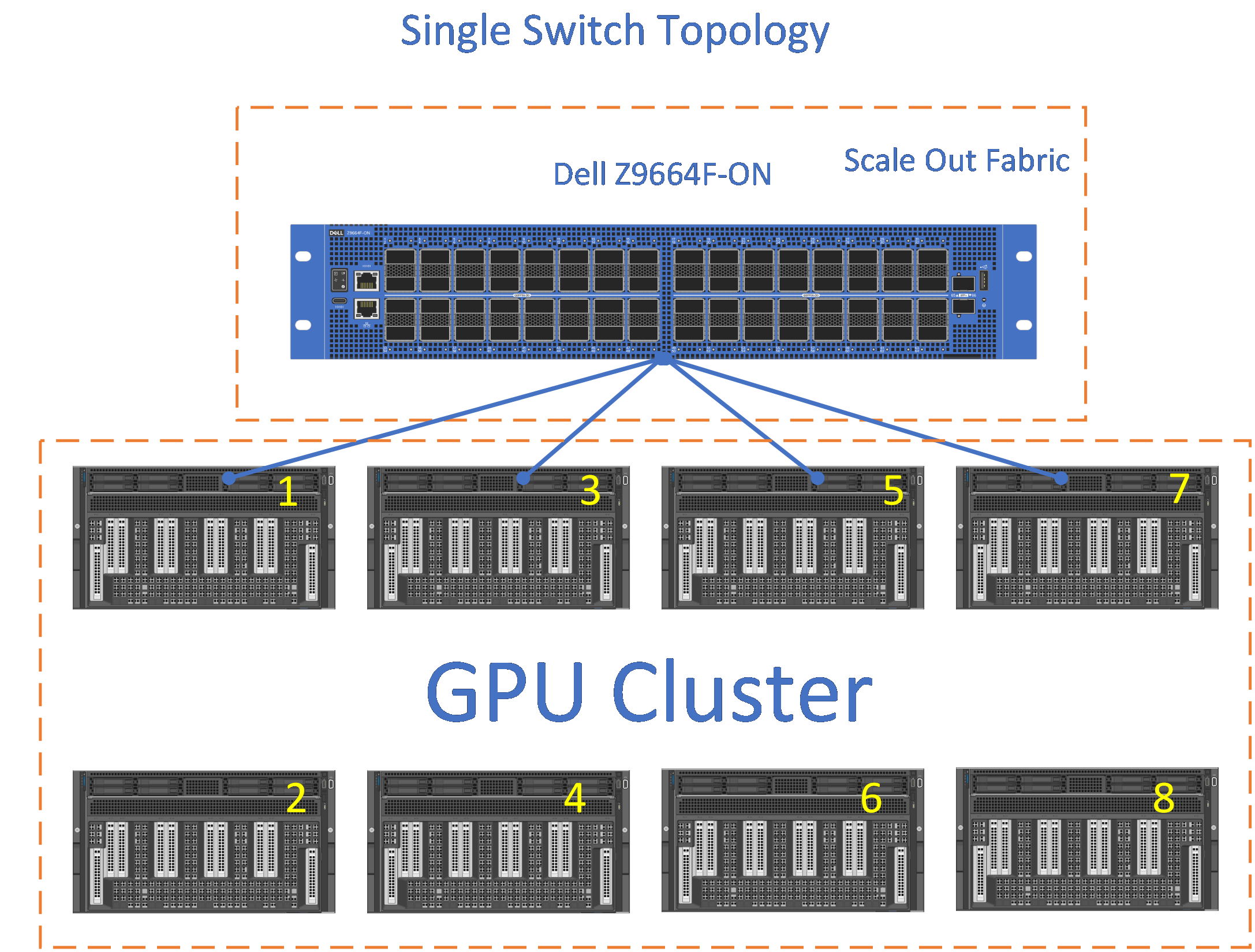
The connections from each GPU to the switch can be 800GbE or 400GbE.
The Z9864F, Z9664F, and Z9423F are the baseline switches to build a Scale Out Fabric based on this topology.
Figure 13 shows a single switch using the Dell PowerSwitch Z9664F with link speeds of 400GbE supporting a 64 GPU cluster deployment.
TOR-Wired Clos topology
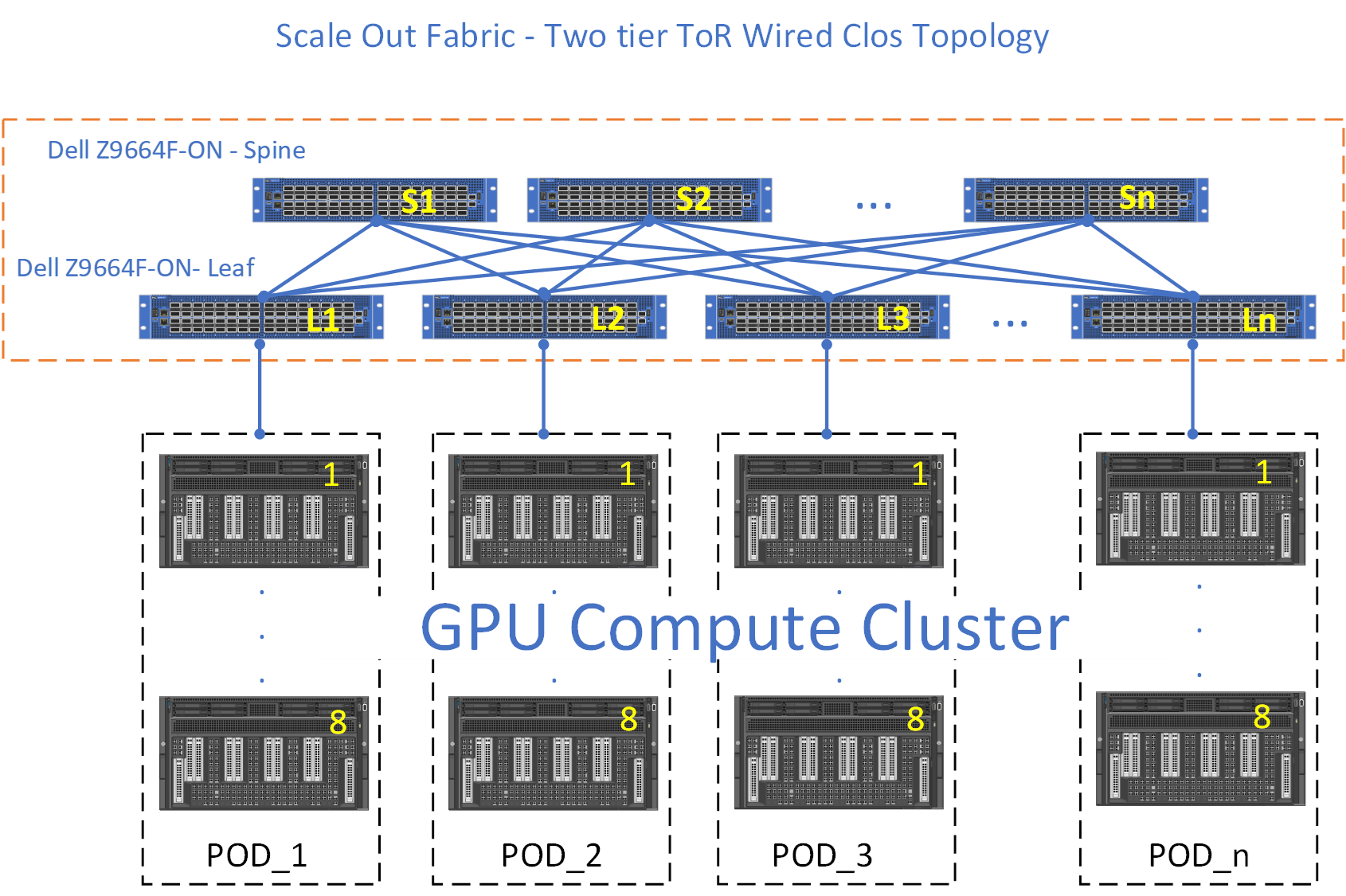
The second Scale Out Fabric topology is the TOR-Wired Clos topology. The connectivity properties of the TOR-Wired Clos topology are shown in Figure 14. This topology enables direct Scale Out Fabric communication between any GPU pairs without involving the Scale Up Fabric, but it is not the recommended topology to build a Scale Out Fabric (see Tradeoffs).
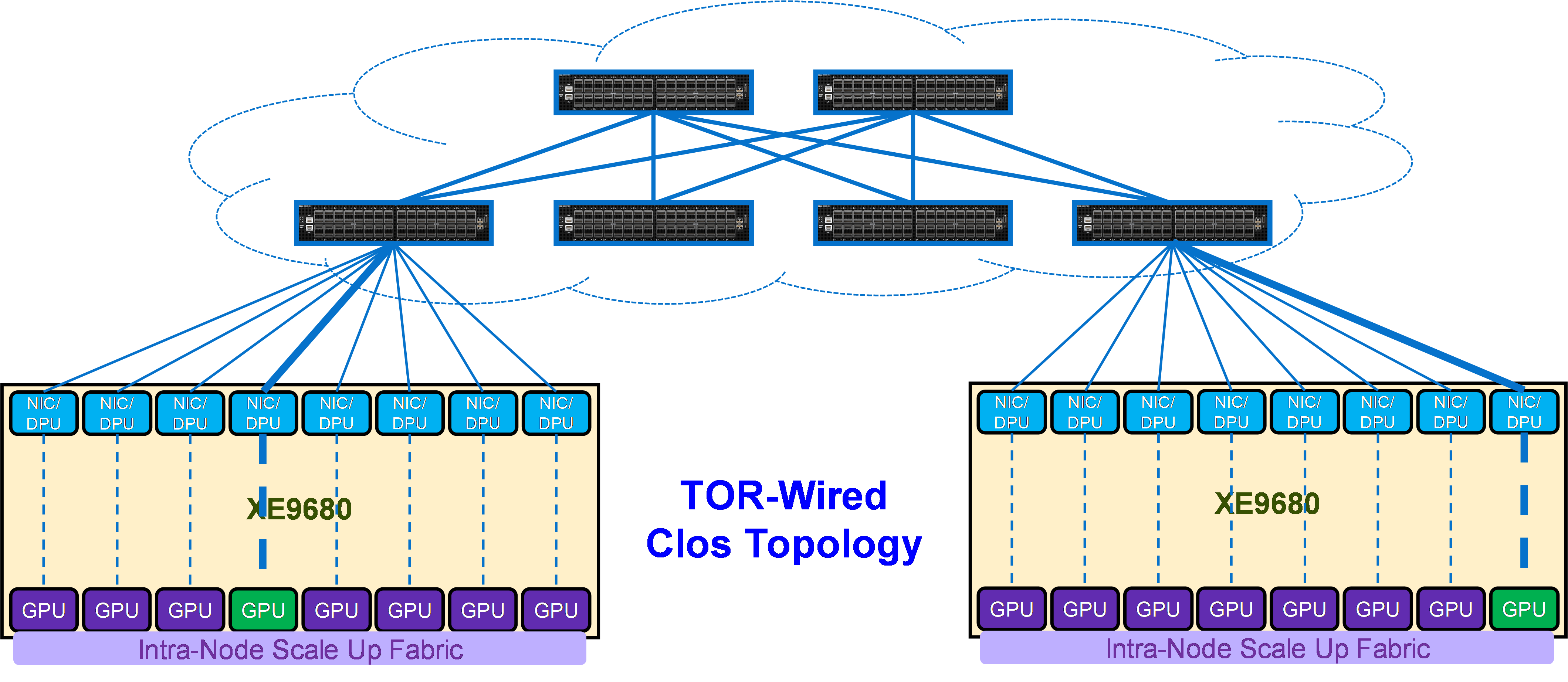
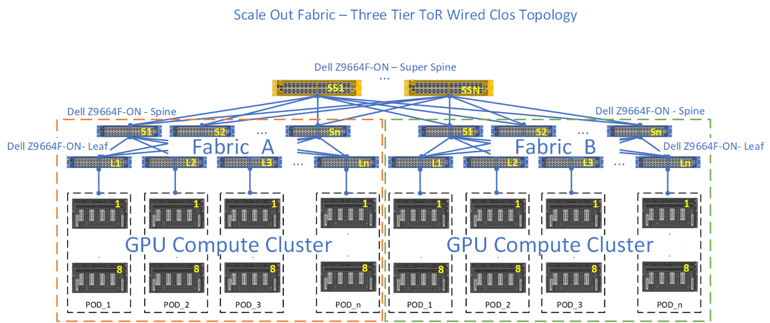
A two-tier leaf and spine ethernet fabric can scale up to a 2,000 GPU compute cluster, whereas with the three-tier leaf and spine architecture, using a super spine tier the compute cluster can go beyond 2,000 GPUs plus enabling the connection of separate subfabrics.
Figure 16 shows two subfabrics (SubFabric_A, and SubFabric_B) interconnected through the super spines.
Pure Rail topology
Figure 17 shows the connectivity properties of the Pure Rail topology.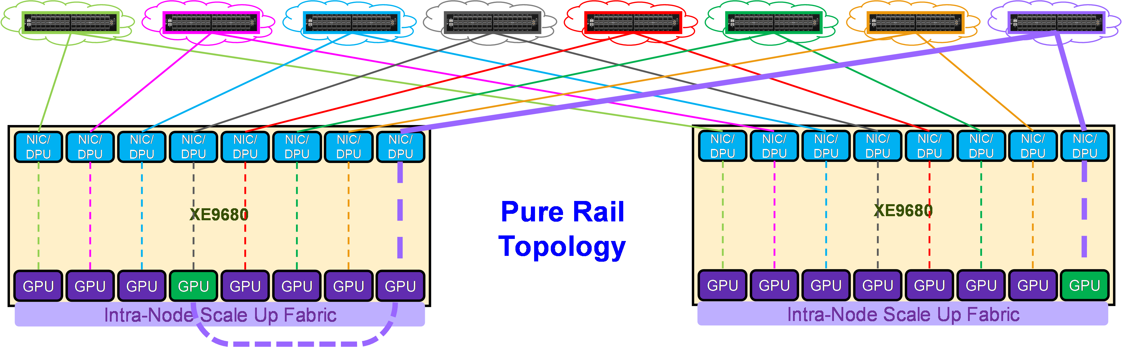
As shown in Figure 17, in this topology, each NIC is connected to a different switch (or spine-leaf network), called a rail. This topology enables direct Scale Out Fabric communication only between GPUs belonging to the same rail. The Scale Up Fabric is involved in the Scale Out Fabric communications to cross rails.
For example, in order to communicate with GPU 8 on server 2, GPU 4 on server 1 has first to transfer its data into the memory of GPU 8 on server 1 (cross the rails), and then GPU 8 on server 1 can communicate through NIC 8 on server 1 with GPU 8 on server 2, coupled with NIC 8 on server 2.
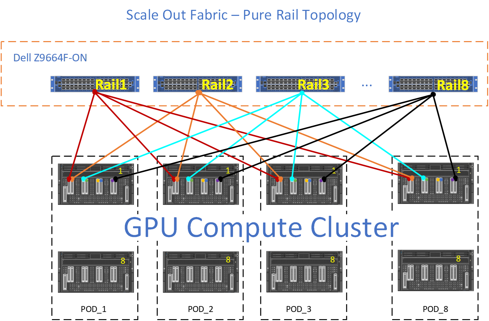
Figure 18 shows an eight-rail topology interconnecting eight PODs. Each POD consists of 8 XE9680. Each XE9680 comes with 8 GPUS. This is a 512 GPU size fabric.
Each GPU from each POD has a dedicated 400GbE connection. For example, Rail1 is a Dell Z9664F-ON switch, with 64 x 400GbE ports. POD_1 consists of eight Dell XE9680, each XE9680 has 8 GPUs, totaling 64 GPUs per POD.
Each GPU 1 from each POD connects to "Rail1," then GPU 2 from each POD, connects to "Rail2," and so on. See Figure 18.
Rail Optimized topology
Figure 19 shows the connectivity properties of the Rail Optimized topology.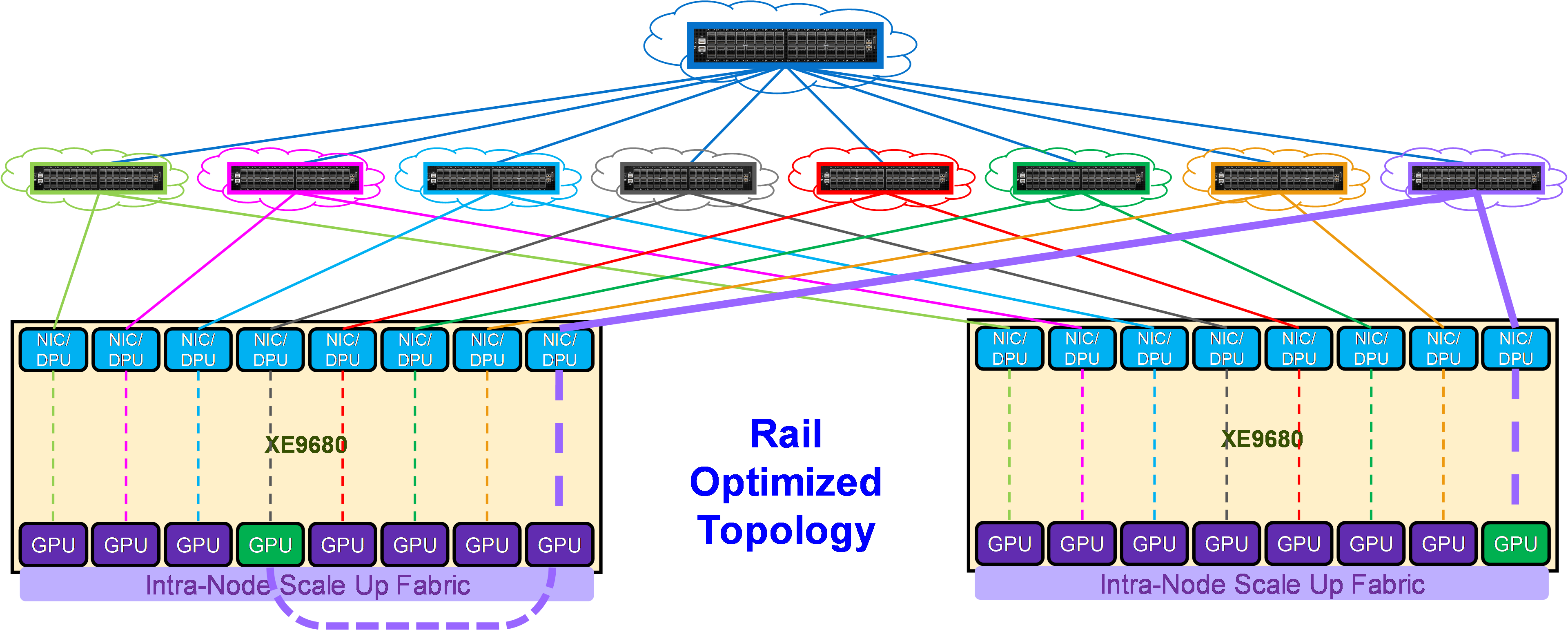
As shown in Figure 19, in this topology each NIC is connected to a different switch (or spine-leaf network), called a rail. The rails are also interconnected at an upper tier. Therefore, this topology provides two ways to cross rails: through the Scale Up Fabric (preferred) or through the upper tier of the Scale Out topology.
For example, in order to communicate with GPU 8 on server 2, GPU 4 on server 1 can either:
- Transfer its data into the memory of GPU 8 on server 1 (cross the rails), and then GPU 8 on server 1 can communicate through NIC 8 on server 1 with GPU 8 on server 2, coupled with NIC 8 on server 2
- Send its data to NIC 4 on server 1, which will be able to reach through the upper tier NIC 8 on server 2, coupled with GPU 8 on server 2.
This property allows AI workloads to perform better on a Rail Optimized topology than on a Pure Rail topology, because the current Collective Communication Libraries are not yet fully optimized for the Pure Rail topology. As such, the Rail Optimized topology is the recommended topology to build a Scale Out fabric (see Tradeoffs in Scale Out Fabric). The Z9864 is the baseline switch to build a Scale Out Fabric based on this topology.
Figure 20 shows an example of Rail Optimized topology with the Dell Z9664F-ON PowerSwitch.
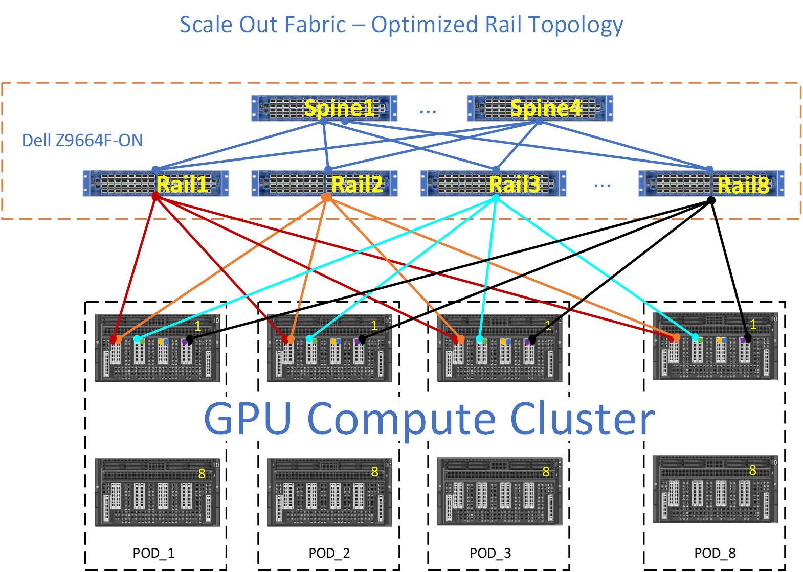
The Rail Optimized topology provides the same set of benefits that a Pure Rail topology does, plus scalability and connectivity through the upper tier (Spine). There are times where the GPU to GPU across different nodes may not take the optimum path (Leaf) and the upper tier (Spine) must provide connectivity between the different rails.
For example, red GPU on NODE_1, POD_1 wishes to communicate with lightblue GPU on NODE_1, POD_3. Ideally, the data path would be for the red GPU to use the internal fabric on NODE_1 to communicate with lightblue GPU on NODE_1, and then lighblue GPU on NODE_1 would transmit this data to Rail3, however, if for some reason this data path is not available, then red GPU will transmit its data upstream towards Rail1. Rail1, will forward towards S1, where S1 will send this data downstream to Rail3.
Tradeoffs
The TOR-wired clos topology allows shorter cables to connect servers to leaf switches in a rack, enabling cheaper DAC cables in place of optical cables.
On the other side, the Pure Rail and Rail Optimized topologies provide better GPU reachability (i.e., more GPUs at 1-hop distance), as shown in Table 2 for the Z9864F-ON and Z9664F-ON switches. This means that these topologies allow better performances for AI workloads, and for this reason they are recommended over the TOR-wired Clos topology.
| Topology | High Bandwidth Domain | 1-Hop Away | 3-Hop Away | ||
| Z9664F-ON | Z9864F-ON | Z9664F-ON | Z9864F-ON | ||
| TOR-Wired Clos | 8 GPUs | 32 GPUs | 64 GPUs | 2048 GPUs | 8192 GPUs |
| Rail | 8 GPUs | 256 GPUs | 512 GPUs (64 nodes) | 16384 GPUs | 65536 GPUs |