
The production topology that is used in this guide is shown in the figure below.
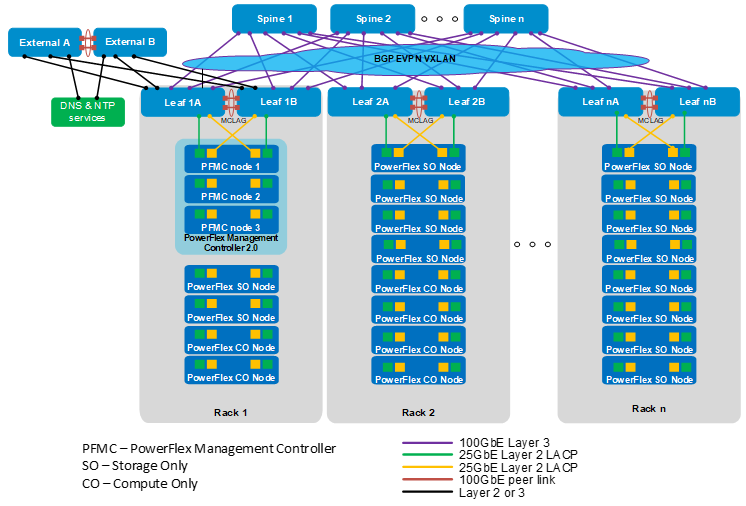
Each rack has two leaf switches connected to each other with a multichassis link aggregation group (MC-LAG) peer link. Every leaf switch is connected to every spine switch to form a leaf-spine (also known as a Clos) topology.
In this deployment example, a three-node PowerFlex Management Controller (PFMC) 2.0 cluster is in Rack 1. The remaining nodes in Racks 1-n are compute only (CO) and storage only (SO) nodes. This deployment uses four 25 GbE network interface controller ports per PowerFlex node for production network connections, as shown in the figure above.
In this deployment example, Leaf1A and Leaf1B are border leafs which are connected to the external switches. The external switches are typically part of an existing network in the data center with DNS and NTP services and Internet or WAN access.
As an option, an additional leaf pair can be added as dedicated border leafs, with no compute or storage nodes connected to them. This option may be beneficial if there is a large amount of North-South traffic between the leaf-spine fabric and the external network. The dedicated border leaf pair must be configured as MC-LAG peers and connected to every spine switch like the other leaf switches in the fabric.
Uplinks from the border leaf switches to the external switches may be configured as Layer 2 or Layer 3. If Layer 3 uplinks are used, you may use Border Gateway Protocol (BGP), Open Shortest Path First (OSPF), or static routing. In the configuration example used in this guide, the uplinks are configured as Layer 3 with BGP.
Equal-Cost Multi-Path routing (ECMP) is enabled on the switches to use all available bandwidth on the leaf-spine connections. Border Gateway Protocol (BGP) Ethernet VPN (EVPN) with Virtual Extensible LAN (VXLAN) is used to stretch Layer 2 networks across the Layer 3 leaf-spine fabric.