
次の図には、このガイドで使用されているプロダクション トポロジーが示されています。
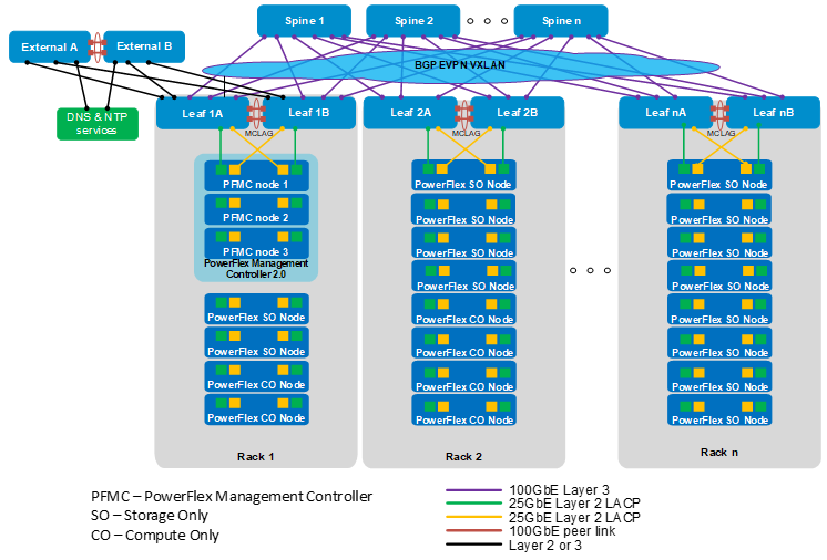
各ラックには、マルチシャーシ リンク アグリゲーション グループ(MC-LAG)ピア リンクを使用して相互に接続されている2台のリーフ スイッチがあります。すべてのリーフ スイッチは、すべてのスパイン スイッチに接続され、リーフスパイン(別名Clos)トポロジーを形成します。
この導入例では、3個のノードのPowerFlex管理コントローラー, PowerFlex Management Controller (PFMC) 2.0クラスターがラック1にあります。ラック1~nの残りのノードは、コンピューティングのみ(CO)ノードとストレージのみ(SO)ノードです。この導入では、前掲の図に示すように、プロダクション ネットワーク接続用に各PowerFlexノード, PowerFlex nodeあたり4個の25 GbEネットワーク インターフェイス コントローラー ポートを使用します。
この導入例では、リーフ1Aとリーフ1Bは外部スイッチに接続されている境界リーフです。外部スイッチは通常、DNSおよびNTPサービス、インターネットまたはWANアクセスを備えたデータセンター内にある既存ネットワークの一部です。
オプションとして、コンピューティング ノードまたはストレージ ノードが接続されていない専用の境界リーフとして、追加のリーフ ペアーを追加できます。このオプションは、リーフスパイン ファブリックと外部ネットワークの間に大量のノースサウス トラフィックがある場合に便利です。専用の境界リーフ ペアーは、MC-LAGピアとして構成し、ファブリック内の他のリーフ スイッチと同様に、すべてのスパイン スイッチに接続する必要があります。
境界リーフ スイッチから外部スイッチへのアップリンクは、レイヤー2またはレイヤー3として構成できます。レイヤー3アップリンクが使用されている場合は、ボーダー ゲートウェイ プロトコル, Border Gateway Protocol (BGP)、オープン ショーテスト パス ファースト(OSPF)、静的ルーティングを使用できます。このガイドで使用されている構成例では、アップリンクはBGPを使用してレイヤー3として構成されています。
スイッチでは、リーフスパイン接続で使用可能なすべての帯域幅を使用するために、等コストマルチパスルーティング(ECMP)が有効になっています。ボーダー ゲートウェイ プロトコル, Border Gateway Protocol (BGP) Ethernet VPN (EVPN)(仮想拡張可能LAN (VXLAN)対応)は、レイヤー3リーフスパイン ファブリック全体でレイヤー2ネットワークを拡張するために使用されます。