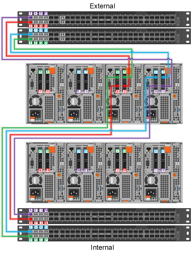
Connect the Isilon nodes to the network, starting with node 1 and ports 1 and 2 on the external and internal switches .
Connect Node 1 on the Isilon to the network in the following manner:
- Port 1 on the Isilon to port 1 on the primary external switch (ext1)
- Port 2 on the Isilon to port 1 on the secondary external switch (ext2)
- Port 3 on the Isilon to Port 1 on the primary internal switch (int1)
- Port 4 on the Isilon to port 1 on the secondary internal switch (int2)