
VCF components
VCF components
-
Each version of VCF includes a Bill of Materials (BOM) which dictates the versions for each component of the solution. VMware offers no ability to substitute. For example, even if there is a newer update for ESXi at the time of installation, VMware requires the version on the BOM. The versions are shown in Table 3.
Table 3. Bill of Material
Software Component
Version
Build Number
Cloud Builder VM
5.2
24108943
SDDC Manager
5.2
24108943
VMware vCenter Server Appliance
8.0 Update 3a
24091160
VMware ESXi
8.0 Update 3
24022510
8.0 Update 3
24022510
VMware NSX
4.2
24105817
VMware Aria Suite Lifecycle
8.18
24029603
Network topology
At the physical layer, two Top of Rack (TOR) switches are used for redundancy and load-balancing purposes. There are four connections from each Dell host, two to TOR A and two to TOR B. VCF requires two of the connections to form the vSphere Distributed Switch (VDS).
The following table shows the different networks that are configured for this solution.
Note: All VLANs are tagged except for management (1109). An untagged VLAN requires setting VLAN ID to 0 in vSphere.
Table 4. Network VLANs
Network type
VLAN ID
Management
0
vMotion
1612
vSAN
1613
NSX Host Overlay
1614
PowerFlex topology
The PowerFlex 4.x system is two-layer, meaning there are separate storage and compute nodes, as HCI cannot be used with VCF.
Storage nodes
There are five nodes for the storage-only configuration. The characteristics of these servers are covered in Table 5.
Table 5. PowerFlex storage node configurations
VCF and compute nodes
The VCF environment consists of seven servers:
- Four for the management domain, which has no PowerFlex components.
- Three for the workload domain. These servers are also the PowerFlex compute nodes.
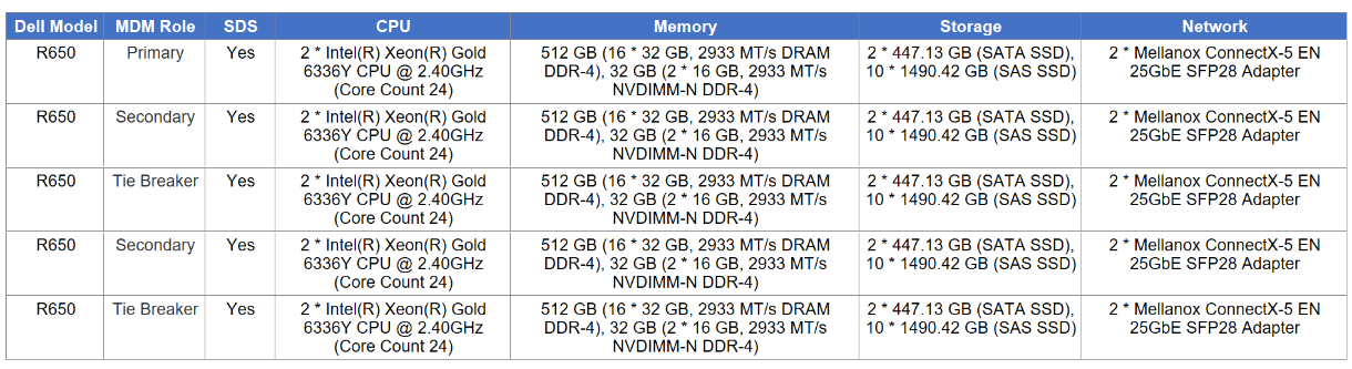
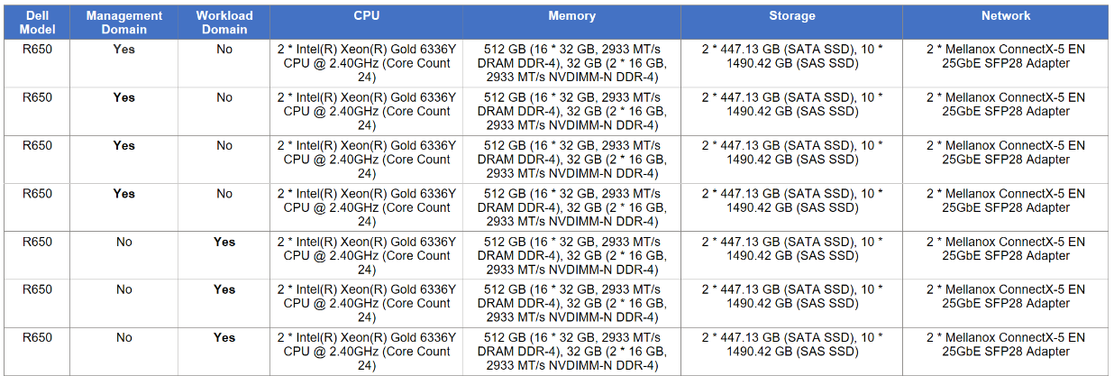
Although the specifications of all servers are the same, they are listed below in Table 6 for completeness.
Table 6. VCF server configurations
vSAN
The VCF 5.2 management domain supports two different implementations of the vSAN storage architecture:
- vSAN Original Storage Architecture (OSA)
- vSAN Express Storage Architecture (ESA)
vSAN OSA is a two-tier architecture that is designed to accommodate both new and old storage devices. vSAN ESA is a single-tier architecture that is built for high performance NVMe based TLC flash devices. Some important differences are:
- vSAN OSA uses disk groups to manage storage while vSAN ESA uses a storage pool configuration.
- vSAN ESA is designed for high performance with its reliance on NVMe devices, while vSAN OSA provides flexibility for various devices.
- vSAN OSA requires more planning to achieve the correct level of performance while vSAN ESA uses the modern disk technology.
VMware recommends using vSAN ESA over vSAN OSA for these enumerated reasons; however, to cover a plethora of configurations, this paper uses vSAN OSA.
vSAN OSA setup
The following are the prerequisites to build the required vSAN storage setup for VCF:
- One SAS or SATA host bus adapter (HBA), or a RAID controller that is in passthrough mode or RAID 0 mode.
- For cache storage: One SAS or SATA solid-state disk (SSD) or PCIe flash device.
- For capacity storage: An All-flash disk group configuration that must have at least one SAS, or SATA solid-state disk (SSD), or PCIe flash device.
Generally, the first bullet point is standard for most servers so that is unlikely to cause a problem with vSAN. For the other two, a known issue exists where VMware is unable to identify devices for use with vSAN during the validation of the Planning Guide. VCF requires a ratio of one cache device to seven capacity devices. If the disks are available and visible on ESXi, but they are not recognized, it is possible to manually assign them as vSAN-eligible. This process consists of two steps, which are outlined below.
Formatting
The first issue is common during the validation step of the install. VMware reports that the devices on the servers have existing partitions, which render them ineligible for vSAN. To determine which devices are problematic, issue the command vdq -qH in ESXi to view all the devices and check the State row. An example is shown in Figure 5:
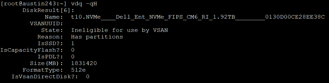
Figure 5. Ineligible for vSAN due to existing partitions
For this particular issue, the solution is to wipe the existing partition. This operation can be achieved by using the utility partedUtil to create a gpt partition on the disk, clearing out the existing ones. The following is an example of the CLI command:
partedUtil mklabel /vmfs/devices/disks/t10.NVMe____Dell_Ent_NVMe_FIPS_CM6_RI_1.92TB________0130D00CE28EE38C gpt
While the command itself does not return any response, running the vdq command once more shows that the State of the disk is now eligible. See Figure 6.
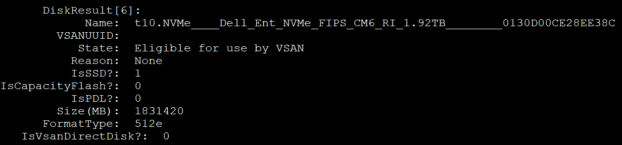
Figure 6. Eligible for vSAN
Capacity compared with cache
The second issue for vSAN occurs when the devices are all the same type, as they are on the servers in this environment. In such cases, VMware treats all the devices as cache storage and leaves no devices for capacity, which is required. This issue appears to be the most common of the two, and impacted the environment detailed in this paper. Fortunately, VMware provides a CLI command to “tag” devices as “capacityFlash” so that VCF claims all tagged devices as capacity devices. It also claims any nontagged devices as cache, satisfying the requirements for building the vSAN cluster. Since vSAN needs at least one cache device, it is best to tag all available devices for capacity, save one. Use the following command to tag devices:
esxcli vsan storage tag add -t capacityFlash -d t10.NVMe____Dell_Ent_NVMe_FIPS_CM6_RI_1.92TB________0130D00CE28EE38C
After running the command in Figure 7 and querying the disk, the “IsCapacityFlash?“ row now shows a positive ‘1’.
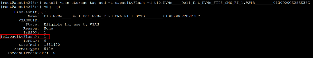
Figure 7. Setting the vSAN capacity tag
With the devices tagged, the Cloud Builder installer can create the vSAN cluster. In this environment, which includes 11 devices, VCF creates three vSAN disk groups for each host. Two of the disk groups have three capacity devices and one cache device. One of the disk groups has two capacity devices and one cache device. One of these hosts is shown in Figure 8.
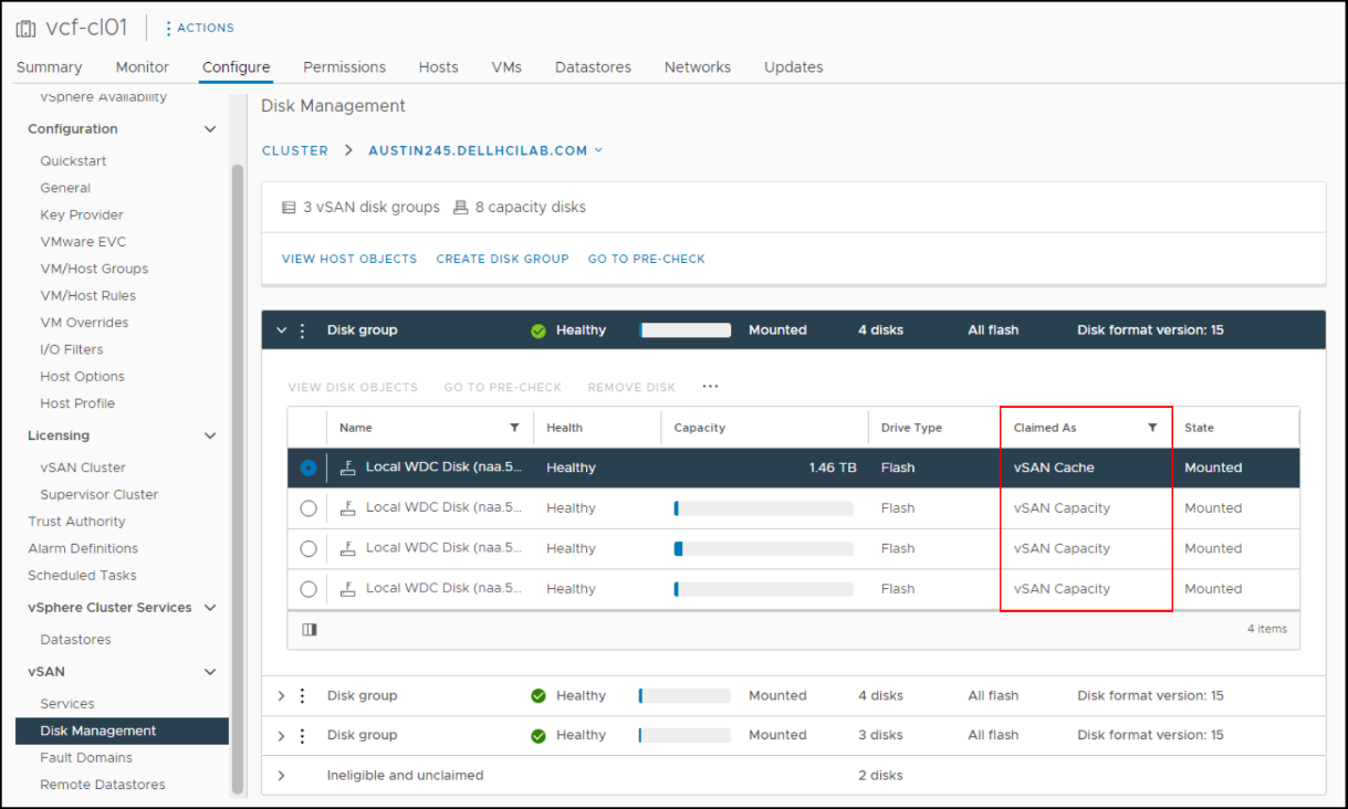
Figure 8. vSAN disk groups in VCF
Domains
VCF uses a concept that is known as “domains.” Domains are essentially a set of resources such as servers, storage, and software. There are two types of domains in VCF: management and workload. There is one management instance per VCF. The management domain is the set of resources that runs VCF. The management domain is the control center of the environment and is responsible for hosting the management plane VMs. The basic management functions are handled through the SDDC Manager, which is the interface to VCF, similar to how vCenter is to clusters of ESXi. The vCenter cannot manage VCF.
Workload domains are deployed from the SDDC Manager and consist of their own vCenter, cluster, hosts, and storage. These workload domains are typically used to run the applications for a business. Unlike the management domain, the workload domain offers great flexibility in storage. Customers with array storage can take full advantage of the features of an array for their applications. The number of workload domains is only limited by the resources available to support them. An example of a VCF instance with two workload domains is shown in Figure 9.
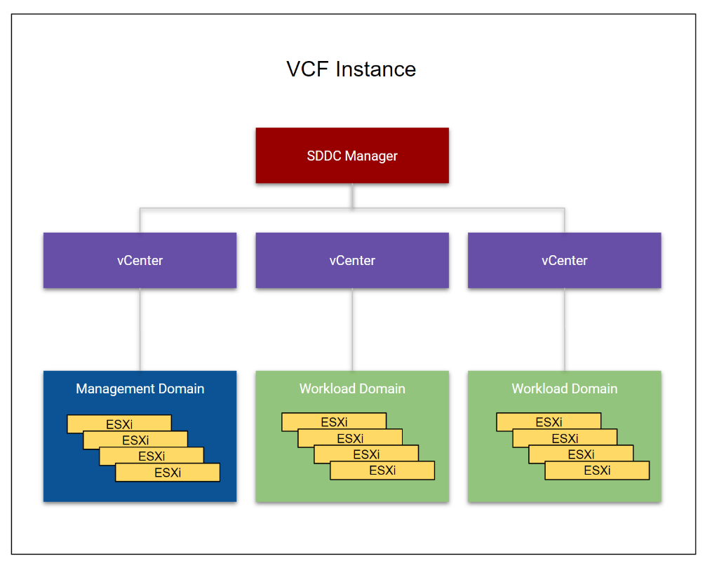
Figure 9. VCF instance with two workload domains
The management and workload domains typically include separate hardware. For customers with fewer server resources or who want a smaller footprint or a POC lab, the management domain can also be a workload domain. This configuration is known as a consolidated architecture and can host customer workloads.
Storage
Storage plays an important role in VCF as vSAN is part of the solution. There are two different categories of storage in VCF, each serving different functions in the solution. They are called principal and supplemental. Principal storage is what is required to deploy a management (vSAN only) or workload domain. It is also required to deploy a new cluster in an existing workload (including the management domain). It can be of type vSAN, VMFS on FC, vVols, or NFS. On the PowerFlex, the SDC qualifies as FC because it installs a software storage adapter which VCF treats like FC. Customers wanting to use SDC for the workload domain would map a device to the ESXi hosts and create a datastore. This datastore is then used in the workload domain wizard when VMFS on FC is the chosen storage. Supplemental storage is the storage that can be added to any existing management or workload domain to offer more space post deployment. Supplemental storage supports all the types of principal storage, including iSCSI and SDC. These storage options are shown in Figure 10.
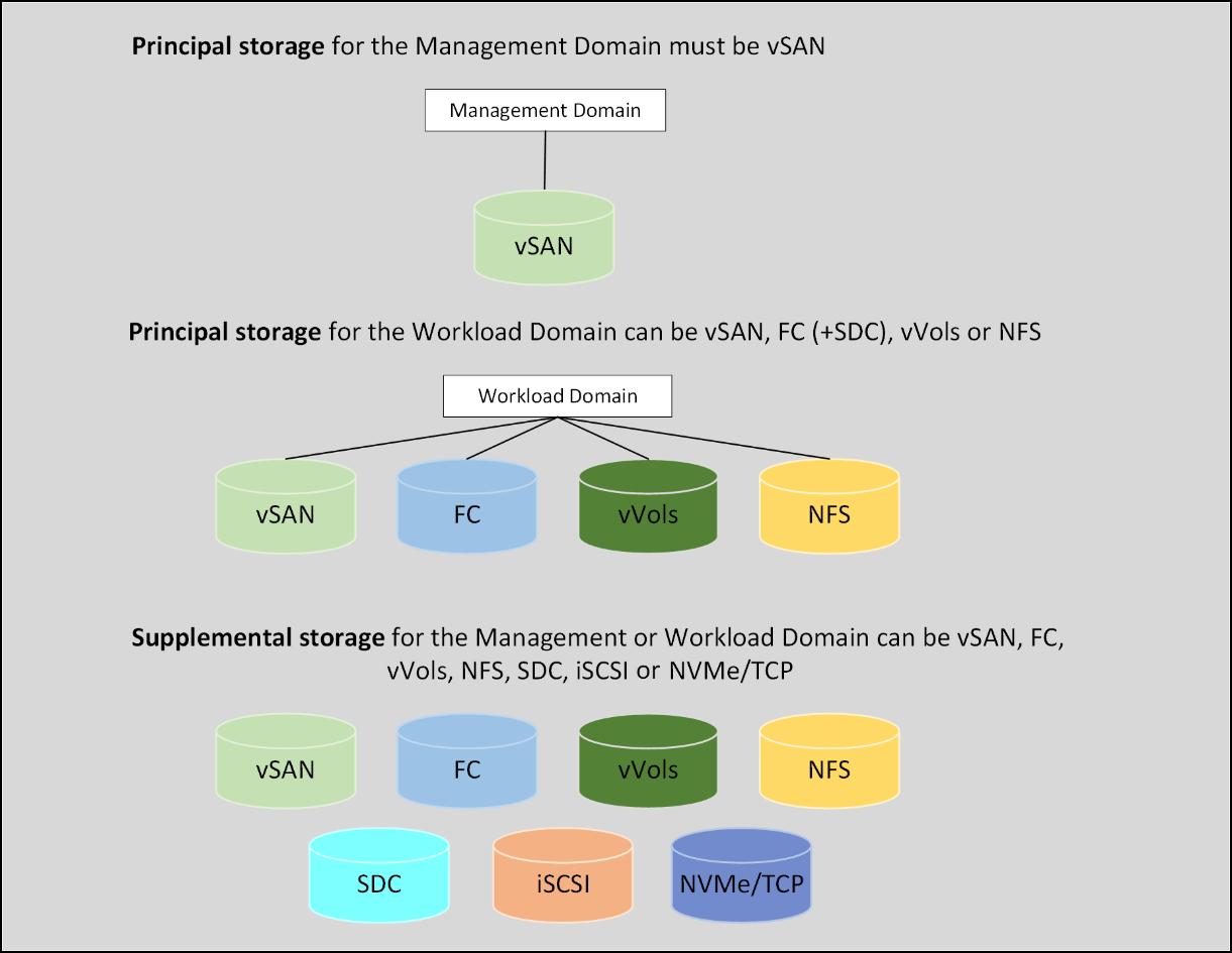
Figure 10. VCF storage options
Note: The SDC is not listed separately in the workload domain since it is acting as FC. It is not shown as a separate option in the workload domain wizard.
As noted, vSAN is the only supported principal storage for the management domain. VMware requires vSAN in the management domain in order to have full control over storage life cycle management from creation to deletion. VCF does not provide this level of control for non-vSAN storage and thus requires the user to manage the life cycle. The entire VCF solution can run on vSAN with no other storage, but at a minimum vSAN must be used to deploy the management domain.
Vendor storage support
VMware does not publish storage support for VCF by vendor, rather they rely on the VMware Compatibility Guide for Storage/SAN. If the vendor is listed as supporting the protocol for the version of ESXi in the BOM, then it is supported with VCF. SDC is not listed for PowerFlex in the guide since it is not a protocol. However, it is still supported for the workload domain as previously explained. The support is instead documented in the following Broadcom KB article: https://knowledge.broadcom.com/external/article?legacyId=55323.
Lifecycle management
VCF has an integrated life cycle management function that facilitates the automation of upgrades to new versions. Because each version of VCF has a specific bill of materials, it is essential to use this function to maintain compliance. The interface is shown in Figure 11.
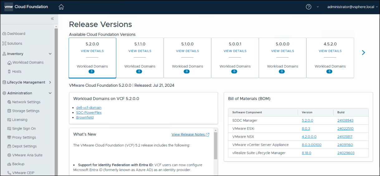
Figure 11. Lifecycle management
PowerFlex
When the workload domain consists of servers that are also compute-only nodes of a two-layer PowerFlex deployment, as in this document, VCF must still control life cycle management. This requirement is due to the strict requirements of the BOM, and in particular the ESXi version. If PowerFlex is allowed to upgrade ESXi outside of VCF, it can render the environment unsupported. Therefore, components like the SDC must be upgraded manually.
VCF recognizes the SDC as a third-party VIB as shown in Figure 12. Unless the major ESXi version is changing, a new SDC is unnecessary as they are backward compatible.
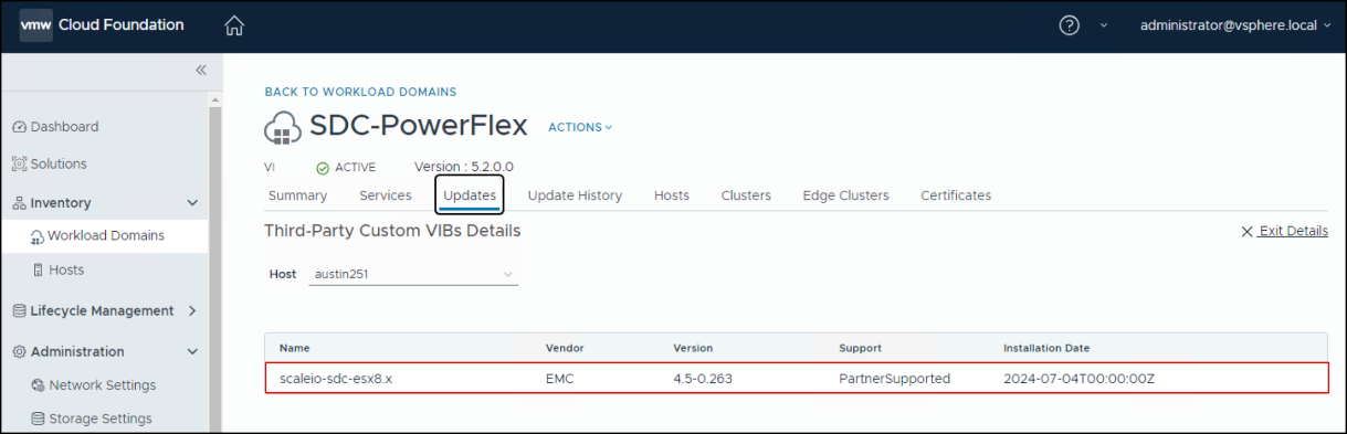
Figure 12. Third-Party Custom VIBs Details
If moving from ESXi 7 to ESXi 8, the SDC must be upgraded before the VCF ESXi upgrade. To do so, prepare each ESXi host by migrating or shutting down any VMs running on datastores that SDC presents. Upgrade the VIB by using the –force option. Here is an example:
esxcli software vib update -d /vmfs/sdc-4.5.0.263-esx8.x.zip –-force
Then upgrade ESXi with VCF.