
Production network connection details for this deployment example are shown in the figure below.
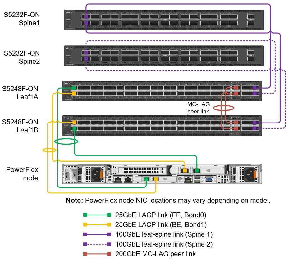
Each leaf switch has one connection to each spine switch. For this deployment, all leaf-spine connections are 100 GbE.
All PowerFlex nodes have two connections to each leaf. The connections in this example are 25 GbE. The four 25GbE connections from each PowerFlex node to the leaf switches are configured in two LACP link aggregation groups (LAGs).
For the MC-LAG peer link connections, two QSFP28-DD double density ports (2 x 100 GbE interfaces per physical port), are available on S5248F-ON switches. They are used to create a 400 GbE port channel that is the MC-LAG peer link. This connection requires QSFP28-DD DAC cables or optics. On switches without QSFP28-DD ports, QSFP28 100 GbE or SFP28 25 GbE ports are used for peer link connections. Dell Technologies recommends using at least two physical ports on each leaf switch for the peer link. This configuration is for redundancy and provides additional bandwidth if there is a failure. The peer link is used for data traffic only if there is a link failure that requires the peer link to reach the destination.