
This guide assumes that the APEX Cloud Platform for Azure cluster and the PowerFlex cluster are both already fully deployed.
The example configuration referenced throughout this implementation guide is based on a 3-node APEX Cloud Platform for Azure cluster and a 4-node PowerFlex cluster.
The PowerFlex nodes are cabled to two ToR switches as shown in the following figure:
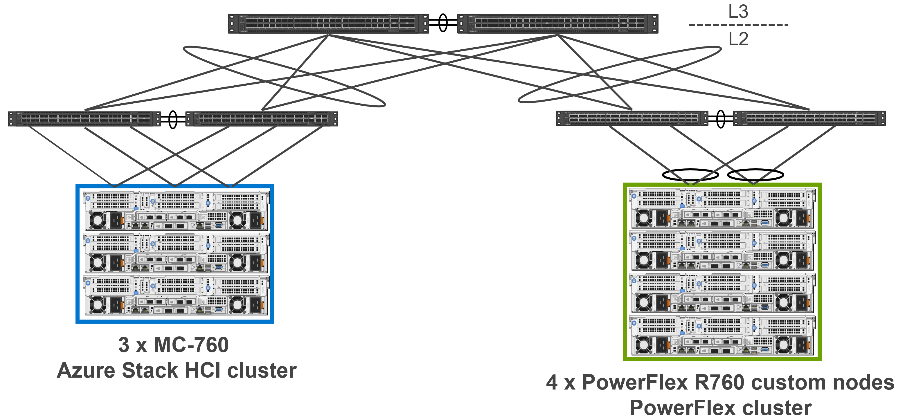
Furthermore, MLAG is used on the ToR switches, creating a VLT Port-Channel connecting to Bond 0, and a separate VLT Port-Channel connecting to Bond 1.Each PowerFlex node contains two dual-port NICs. The ports from one NIC are cabled to one ToR switch, and the ports from the other NIC are cabled to the other ToR switch. To enable High Availability, the design uses networking bonding and MLAG. One interface from each NIC is added to Bond 0 and the other interface from each NIC is added to Bond 1.
The following diagram depicts the topology:
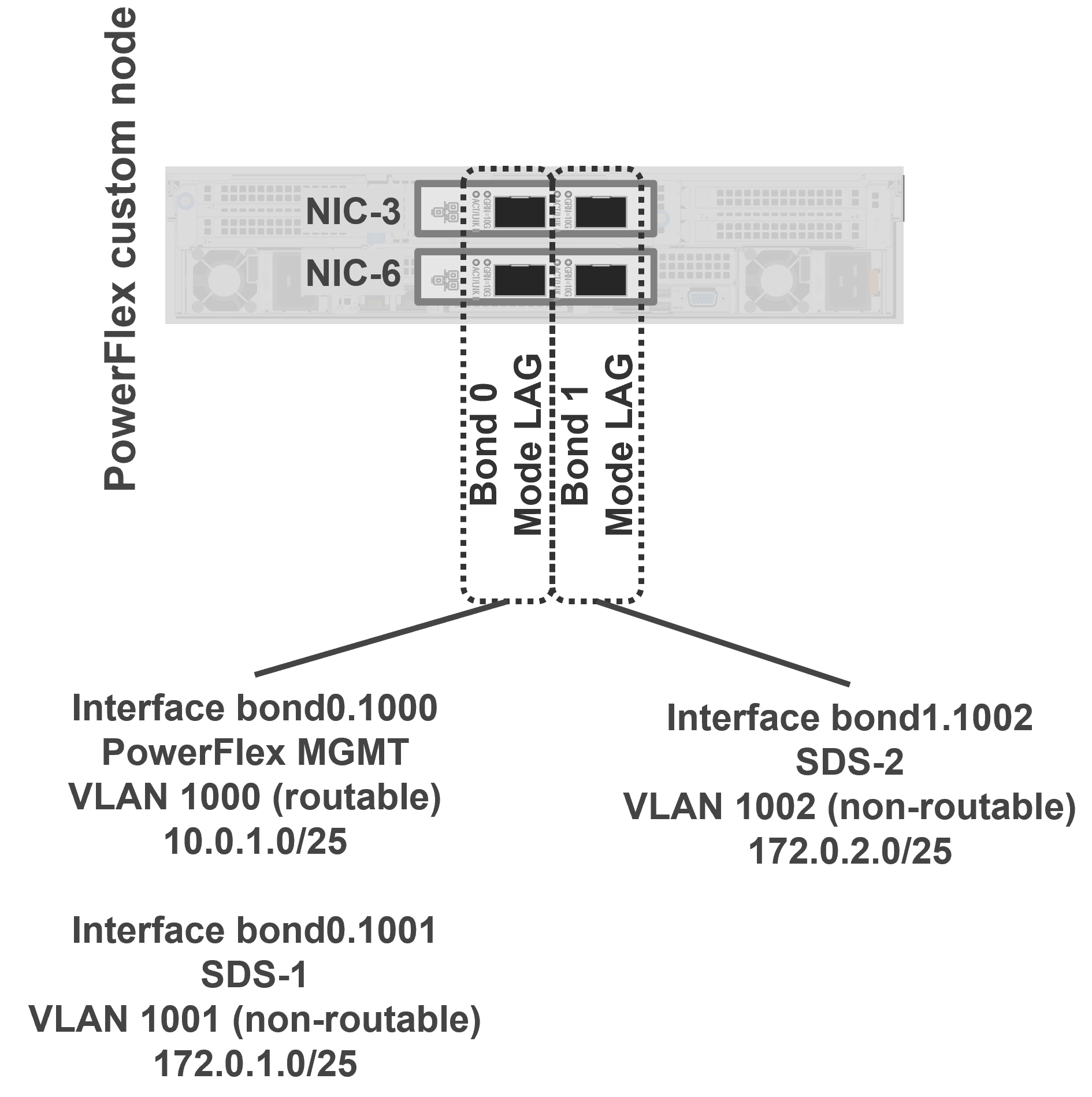
In our example, Bond 0 is configured with both Management (VLAN 1000) and SDS-1 (VLAN 1001) networks, while Bond 1 is configured with the SDS-2 (VLAN 1002) network.
For additional details, see the corresponding Design Guide - Consuming PowerFlex Block Storage from Dell APEX Cloud Platform for Microsoft Azure.